

I had a little mishap with my extruder head. In my absence the Proximity sensor had broken off and got tangled near the hot-end. Suffice it to say, that was the end of it.
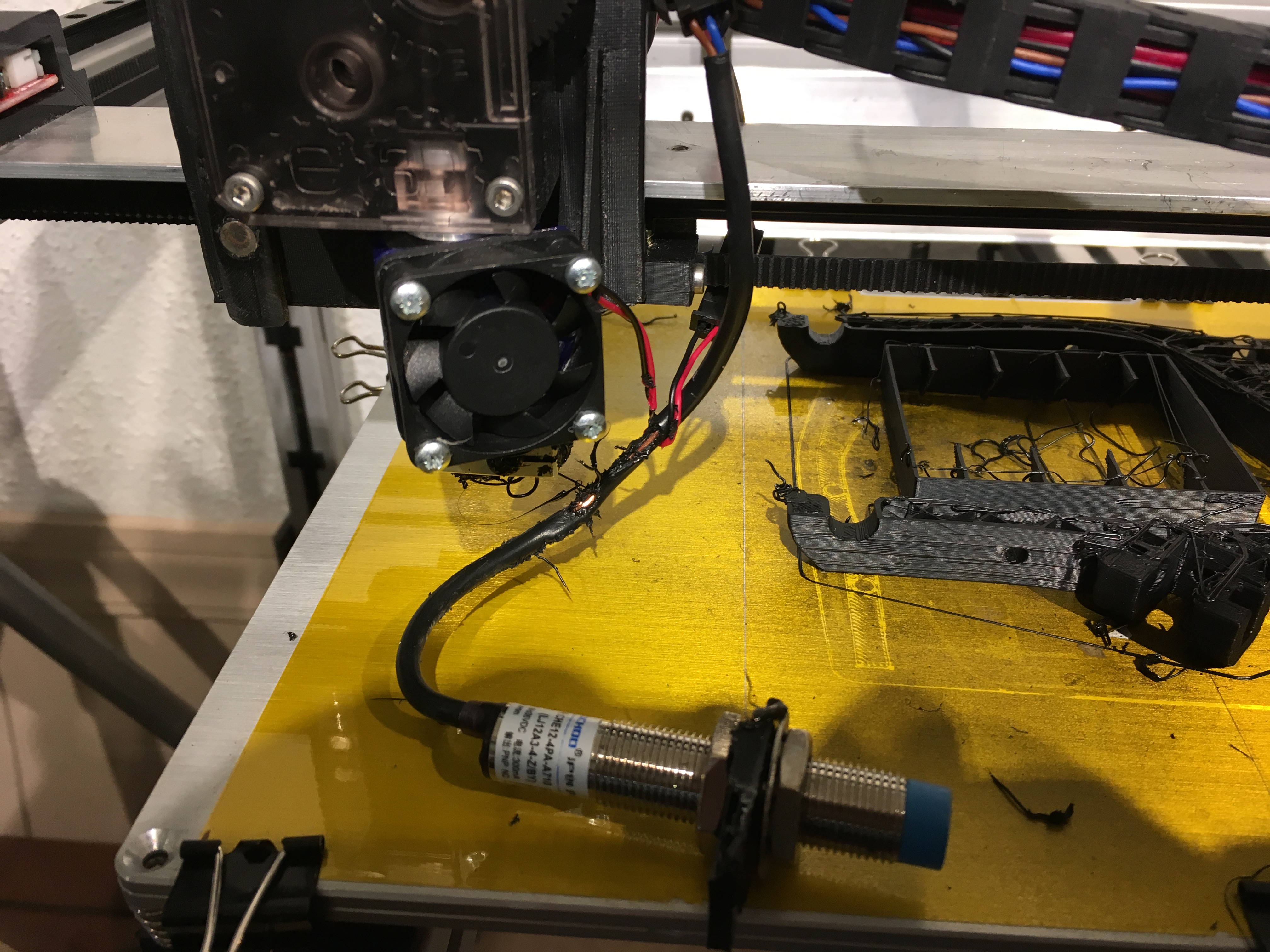
The destroyed sensor was a DIYmall LJ12A3-4-Z/BY Proximity Switch DC 10-30V PNP I bought on Amazon(Yes I’m an affiliate).
The sensor takes in 12 volts and comes with a voltage regulator that reduces the signal to 5 volt(ish). I personally like the voltage regulator as I don’t have buy bulk resistors just to get 2 resistors soldered on.
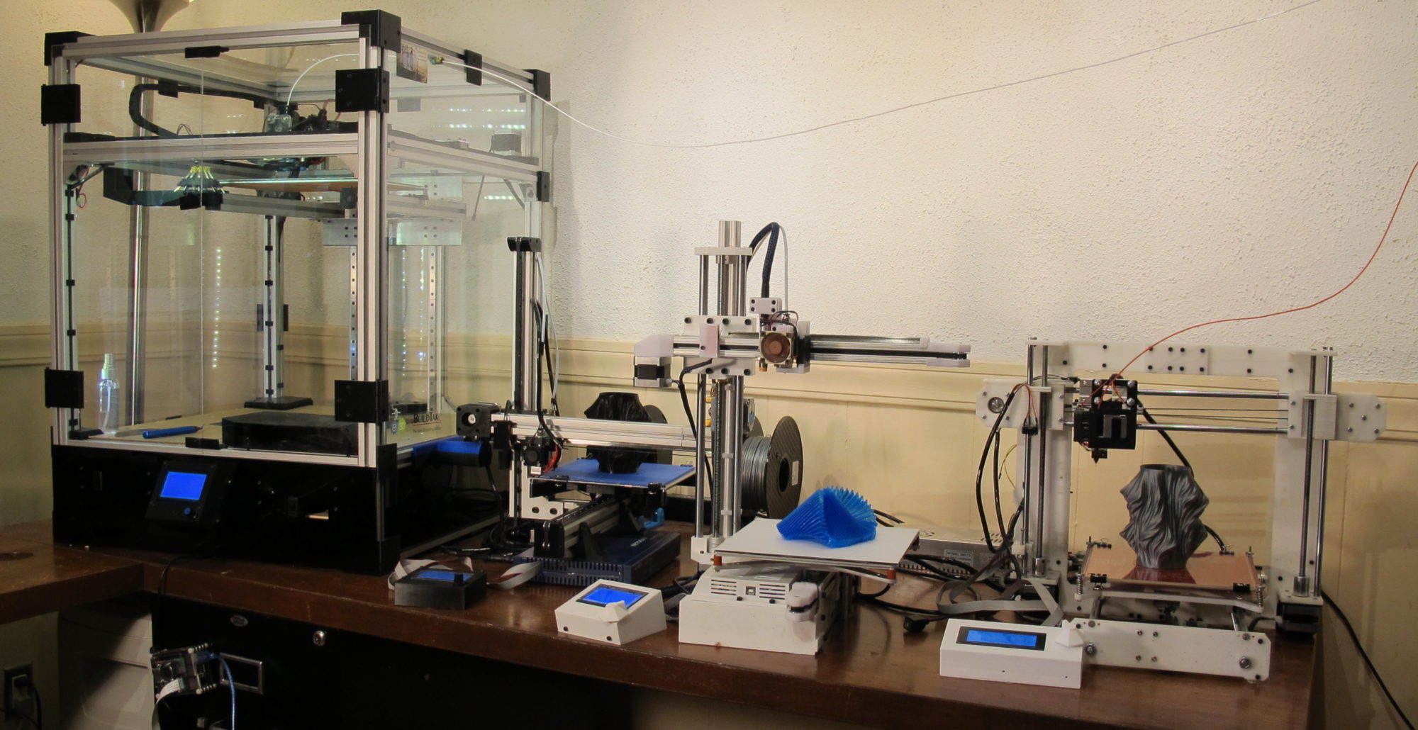
Here is how the LJ12A3-4-Z/BY was wired and how it worked for me for some time. And yes I do love the auto leveling feature.

Alternatively you can use the resistors:

Now that it was broke, I had to replace it with my spare sensor but it did not work as expected. I wired up the sensor in the same manor and got the little light to work as expected when approaching the sensor with a metal object.
Marlin however kept reading the z-min as triggered, regardless of what the little light on the sensor indicated. I even went into the firmware and futzed around with the Z_MIN_ENDSTOP_INVERTING but to no avail. No surprise as the z_min was triggered regardless of signal.
Turns out the spare sensor I had was NOT the LJ12A3-4-Z/BY but instead it was the LJ12A3-4-Z/BX (that’s right, I’m affiliated here as well). This where things got a little complicated.
Every site you visit on wiring references either the voltage regulator or resistors (actually resistors seems to be the more prevalent way of implementation).
Even in the case of the LJ12A3-4-Z/BX I’ve seen the schematics using the resistors. For some reason the LJ12A3-4-Z/BX does not seem to work with the voltage regulator and it might work with the resistors but I really DON’T NEED either.
The specs for the LJ12A3-4-Z/BY are as follows: DC 10-30 Volt
The specs for the LJ12A3-4-Z/BX as follows: DC 6-36Volt
Instead of connecting the sensor to the 12 Volt input (like required for the BY) the LJ12A3-4-Z/BX can be connected to the 5 Volt output on the actually stop. The 5 Volt is enough to get the proper signal (even though the specs state 6-36V).

UPDATE: Today I tried connecting my second LJ12A3-4-Z/BX to a KFB2.0 board and IT DID NOT WORK using the 5 volts. I ended up using the resistor method (above) using 2K and 1K resistors.
The reason it may not have worked this time could be explained by one of two ways:
- Not all LJ12A3-4-Z/BX are created equal, anecdotal information out there seems to indicate this
- The KFB board outputs 4.9 volts as opposed to the 5.1v on my previous RAMPS 1.4 board. I’m wondering of this little difference may just put it too far from the 6 Volts required.

I have the one labelled as “BY” and it has a blue plastic cap on the tip and its labelled as 6-36V. Haven’t tried to hook it up yet on my new build. Confused by the different labelling on various devices with the same model number. I was hoping for a plug-n-play sensor.