The C3Dt/bd (Big Delta)

This all started with 3 THK linear rails I found on eBay. SR15 Genuine THK at 1630mm long. Price $450. I added it to my eBay list and went back and forth probably 50 times before I went ahead and clicked Buy Now.

3 linear rail = Delta

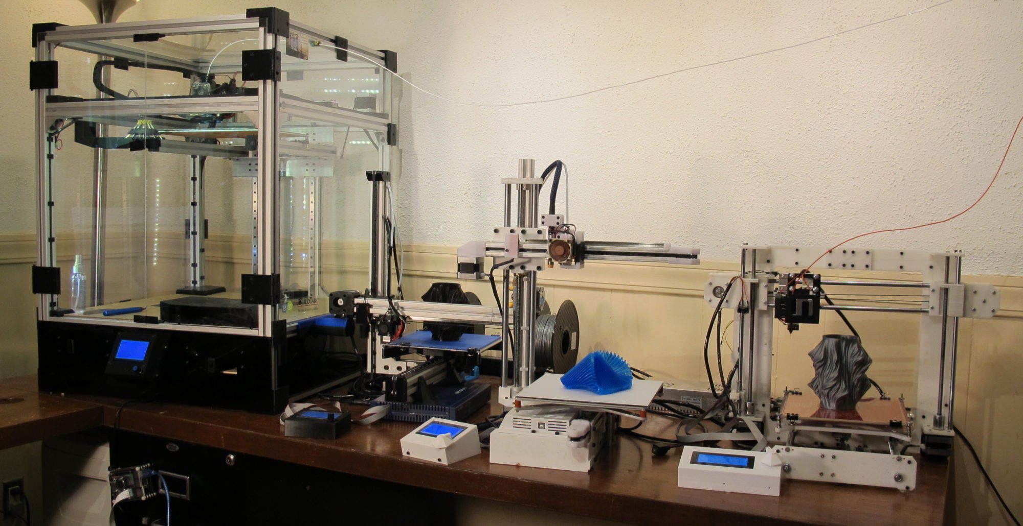
I’ve now designed and implemented 4 printers. One I3 Clone (to get my feet wet), a CoreXY and two cantilevers (C3Dt/n and C3Dt/c). This is, and will remain, a hobby for me so I like to try new things. Delta Kossel, is something I hadn’t done yet, so regardless of it’s pros and cons (much debate on this); a Delta it is. A BIG delta with one additional feature that I’m pretty hasn’t been done before (one I’m gonna keep to myself for now but all will be revealed at MRRF2019 (Mid West RepRap Festival 2019).

Here’s a clue about the new feature (x3)

Specs

For this printer I wanted to go big foremost but I also wanted to get good parts. I’m limiting myself this time in getting stuff directly from China).

  • Build volume: 320mm x 1220mm
  • Hot-end E3D V6 (Threaded for Effector)
  • Controller: Duet Wifi
  • LCD: PanelDue 7″ touch screen
  • Delta Smart Effector (with touch sensor homing)
  • Drive: Nema 23 for X Y and Z, Nema 17 for Extruder
  • Heated bed 110V
  • Linear Rail SR15 (THK)

Given Nema 23 and THK rails, speed should be possible (Although, I’m not a true believer of 3D printing and speed).

Current state and first impressions

I’m now about 80% into the build and I’ve already learned a few valuable lessons.

Aluminum extrusion alone won’t do it

I’m using 4040 Aluminum extrusion at 2000mm height. I’m using brackets I found on ebay that accomodate this size but these aren’t very strong. I quickly learned, the frame alone does not offer enough support to make this a stable printer. Regardless of the weaker corner joints, simply the length of the extrusion introduces a torsion that is problematic. I’ve bolted 2 of the 3 frame supports to my wall and built-in desk which has solved this issue. I’m not entirely sure how to handle this when showing at MRRF2019. I wonder if tripod legs from the middle down would help.

Delta Printers by nature sacrifice a lot of height

Even though the linear rails are 1630mm long, I don’t think I’ll achieve more than 1220 Print height. The effector arms simply take up a lot of space. I will be using 360mm long effector arms ( I believe the least I can get away with with a 330mm bed) so at most there’s 1630-360= 1270mm

add to that the actual height of the effector and hot-end at 58mm that leaves 1210mm (All this time I thought it was 1220, dang, lost another centimeter).

Lots of wire

At the moment the plan is to run the hot-end wiring though the top of the printer (might might change that idea) which means lots of wire. The Delta Smart Effector hooks up to 18 wires

  • 2 wires for heat sink fan
  • 2 wires for hot-end
  • 2-4 wires for thermistor
  • 2 wires for parts cooling fan
  • 4 wires for Z probe
  • 4 wires for Extruder (yes I’m planning a flying extruder, only inches above the hot-end)

All these 18 wires have to make it all the way to the top of the printer (say 2,000-300= 1,700mm) plus some way down again to the controller board (let’s say another 1,000mm). I’m not putting the electronics in the top of the printer because I can’t reach it (duh). I’m not putting it below the bed because of the 110V bed heating pad.

Then there is the 3 wires for each end-stop (X,Y and Z) at let’s say 1,400mm

The 3 stepper motors at the bottom of the printer. I decided to put them at the bottom as three Nema 23 motors are quite heavy (better have a heavy base than top). so there’s another 4×3 wires at another 1,400mm.

4 wires for the heated bed (2 power, 2 thermistor) at 1,000

So we’re looking at a total of at least:

(14*2,700)+(3*3*1,400)+(3*4*1,400)+(4*1,000) = 71,200mm = 71 Meters of wiring.

right now practically all wiring is 22 awg (including hot-end wires) and I hope that will do (of course not the 110V wires).

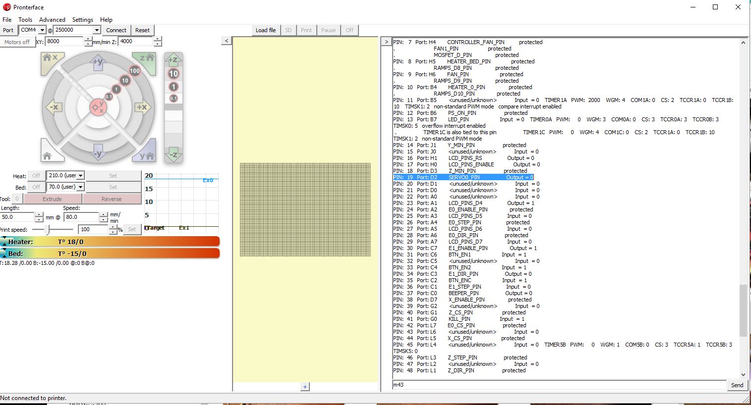
Duet is pretty awesome

I’m still not entirely over the guilt of moving from marlin to RapRapFirmware but the documentation provided by Duet is very comprehensive and has yet to let me down.

I purchased the PanelDue 7″ and in hindsight that may have been overkill. You basically get a slimmed down UI from the web interface which really is all you need.

The Delta Smart Effector is a nifty little device. One wired up (as seen in the image), I can see it easily swapable for another (basically two connectors and a bowden tub).

Where am I now

As of this writing I’d say 80% of the printer is done. Frame is done, I have Duet Wifi wired up. Effector is in place, Hot-end heats up.

I Still need to add an extruder. I’d like to get my hands on a BondTech BMG but I’ll need to help from them (or a donor). If not I’ll probably start out with a simply MK8 implementation.

Well there you have it. The Delta build to date. The current price tag is now up to $1,400 and climbing. If you have the means to support me, please check out my Patreon page at https://www.patreon.com/Core3d_tech

Stay updated on my tweets at @Core3d_tech or on facebook at https://www.facebook.com/Core3D.tech/

My next post will probably show the first test prints (or at least calibration).

Connecting BLTOUCH to KFB2.0

A quick tutorial on how to connect a BLTOUCH to KFB2.0. The reason this is slightly different from other boards is because KFB2.0 is missing dedicated Servo pins.

In order to figure this out I ordered a genuine BLTOUCH from Amazon, so if you’re using a clone, this should probably still work but no guarantees.

The BLTOUCH consists of 2 sets of wires. The end stop wires and the servo wires.

The end stop wires will go into the regular end stop connectors but for the servo wires we need to use an alternative to get around the missing servo pins

There are many parts required to wire up a KFB2.0 but for this instructable you will need at least

BLTOUCH Amazon $37.98 (no extended wires, get extended if you need them)

KFB2.0 Amazon $19.57

For this setup we’re going to use/abuse the Z-Max end stop connector to run the servo on the BLTOUCH

Z-Min is used as the actual end stop

The picture says it all. Connect all 5 wires from your BLTOUCH according to the image with the Servo wires being handled by the Z-Max connector.

In the software setup we’ll redirect the pins

A few changes have to be made to enable the BLTOUCH and redirect the pins

In Configuration.h

Pick the MKS_GEN_L board for the KFB2.0

#ifndef MOTHERBOARD<br>  #define MOTHERBOARD BOARD_MKS_GEN_L
#endif

Practically all of the following settings are a matter of uncommenting/commenting your code by adding/removing // (adding these will disable code)

For this setup it is assumed you will be using the Z-Min for the Z endstop

#define USE_XMIN_PLUG<br>#define USE_YMIN_PLUG
#define USE_ZMIN_PLUG

define your ENDSTOPPULLUPs, make sure it uses ENDSTOPPULLUP_ZMIN_PROBE

#define ENDSTOPPULLUPS<br>#if DISABLED(ENDSTOPPULLUPS)
  // Disable ENDSTOPPULLUPS to set pullups individually
  //#define ENDSTOPPULLUP_XMAX
  //#define ENDSTOPPULLUP_YMAX
  //#define ENDSTOPPULLUP_ZMAX
  #define ENDSTOPPULLUP_XMIN
  #define ENDSTOPPULLUP_YMIN
  //#define ENDSTOPPULLUP_ZMIN
  #define ENDSTOPPULLUP_ZMIN_PROBE
#endif

for my BLTOUCH installation I have the inversion set to false

#define Z_MIN_PROBE_ENDSTOP_INVERTING false // set to true to invert the logic of the probe.

let the system know it uses the probe for Z-min

#define Z_MIN_PROBE_USES_Z_MIN_ENDSTOP_PIN

turn on BLTOUCH

#define BLTOUCH
#if ENABLED(BLTOUCH)
  #define BLTOUCH_DELAY 100   // (ms) Enable and increase if needed
#endif

The following setting are going to depend on where you have mounted your BLTOUCH. Measure the distance from your BLTOUCH pin to your extruder. These values make sure you remain on top of your bed when auto leveling. The values below may (and probably won’t) match your setup

#define X_PROBE_OFFSET_FROM_EXTRUDER 48  // X offset: -left  +right  [of the nozzle]
#define Y_PROBE_OFFSET_FROM_EXTRUDER -2  // Y offset: -front +behind [the nozzle]
#define Z_PROBE_OFFSET_FROM_EXTRUDER 0   // Z offset: -below +above  [the nozzle]

set probe speed

#define XY_PROBE_SPEED 8000

IF you want the probe to do a double touch (or more)

#define MULTIPLE_PROBING 2

The following setting will position your extruder prior to during and after probing

#define Z_CLEARANCE_DEPLOY_PROBE   15 // Z Clearance for Deploy/Stow
#define Z_CLEARANCE_BETWEEN_PROBES  10 // Z Clearance between probe points
#define Z_CLEARANCE_MULTI_PROBE     5 // Z Clearance between multiple probes
//#define Z_AFTER_PROBING           5 // Z position after probing is done

Make the system aware of at least this servo

#define NUM_SERVOS 1 // Servo index starts with 0 for M280 command
#define SERVO_DELAY { 300 }

If you are going to use the BLTOUCH for Auto Bed Leveling set the next values

#define AUTO_BED_LEVELING_BILINEAR

Since the KFB 2.0 does not have its dedicated Servo pins we using the X-Max plug to power the servo that is inside the BLTOUCH.

For this we need to tell the Marlin firmware to redirect some pins.

It is assumed you have selected BOARD_MKS_GEN_L in the configuration.h

open the file pins_MKS_GEN_L.h

in it add the following Make sure you add this AFTER the line #include “pins_RAMPS.h”:

#include "pins_RAMPS.h"
//redirect the servo pin to the X-Max plug
#define SERVO0_PIN 19

If you want to test the pins with g-code m43 you’ll need to enable #define PINS_DEBUGGING in configuration_adv.h

#define PINS_DEBUGGING

Once you’ve uploaded the updated Marlin FW to the board you can test the BLTOUCH.

If your firmware is setup for Safe Z-homing (meaning you can’t home z before having homed X or Y) you either need to turn this feature off in the firmware

in configuration.h comment out Z_SAFE_HOMING

//#define Z_SAFE_HOMING

or have your X and Y end stops connected.

First test is to see what happens with you turn on/power up your board. In this setup the BLTOUCH lights up when powering on and does two servo action. The probe pin comes out twice and retracts

As far as lights is concerned I see the orange light and a small purple led on. (not quite clear in the photo)

connect to the board with something like PronterFace or OCtoPrint and send it g-code m43 (if you’ve enabled PINS_DEBUGGING in the last step)

Check to see if pin 19 is indeed set to SERVO0_pin

Next check out this video for testing the BLTOUCH setup

If this was useful to you in anyway, please consider supporting me through Patreon  or making a small donation here.

3D Printer 24 Volt Upgrade

The Core XY I built and have been gradually upgrading is a beast but it still runs on 12 volts. It runs on a plain RAMPS 1.4 recently upgraded with TMC2130 stepper drivers.

It’s possible to upgrade a RAMPS 1.4 to 24 Volt but it seems easier to go with a 24 Volt board off the shelf. In my case a KFB2.0 (very close relative to the MKS GEN L).

Why upgrade? Well, from all I’ve read, it provides more torque to the stepper motors and it also seems that TMC2130 don’t run well in spreadcycle with 12Volt. Supposedly, the Spreadcycle should get a bit more quiet with 24 Volt.

What will change

Power Switching Unit

Obviously the existing 12 Volt Power switch will be replaced with a 24 Volt one. $19.98 on Amazon: https://amzn.to/2JevH8i Other than the Sticker on the outside stating 24V/15A instead of 12Volt/30A, there is remarkable little difference between the two units (both outside and inside).

Once I ordered the 24Volt power switching unit and hooked it up, I noticed the cooling fan came on immediately. That’s annoying as I want my 3D printer to be quiet in Idle mode.

24 Volt heating cartridge

The heating cartridge inside my hot-end is rated for 12 Volt. It needs to be replaced with a 24 Volt Cartridge. From what I’ve read, on keeping a 12, Volt cartridge, it’s simply not worth the risk. Apparently, the power provided to the 12 Volt Cartridge would quadruple and thus could cause melting the entire heat block. There’s tricks that can be done with PWM sent to the heater but again it’s not worth the risk.

I own a genuine E3D Titan Extruder with E3D hot-end, so I ordered mine directly at e3d-online.com. There are plenty of knock-off on Amazon at $8.99 https://amzn.to/2sDa1s0 (I payed about the same ordering from e3d-online).

Heated Bed

My CoreXY printer runs a 110 Volt heated bed controlled though an SSR so there’s no issue upgrading to 24 Volt (See my instructable on this at instructables.com). The SSR input can handle 3-36 volt.

That said many of the MK2B beds can handle both 12 volt and 24 Volt. It’s just a matter of how to connect the wires.

Cooling Fans

The fan in the power unit is kinda loud so I wanted to replace that right away. I’m a huge fan of the Noctua 40mm cooling fans (their practically noiseless) (Amazon $13.95 https://amzn.to/2HsZdS8).

So I’m replacing all my fans with Noctua Fans. I have 2 80mm fans; one that cools the electronics compartment and one that sits about me stepper which provides for active cooling of my TMC2130 stepper drivers (amazon $15.95 https://amzn.to/2JpABLS).

Then there is the 60mm cooling fan that sits inside the power switching unit so I ordered a 60mm one (Amazon $14.95 https://amzn.to/2Jl49Ke).  Small problem with this fan is that it only comes in 60x25mm. It will not fit inside the power unit. Instead it will be mounted on top. Frankly, I was a bit disappointed at how, it is not as quiet as the 40mm ones. Little more measuring showed more than 12 Volt was passed through the fan. It works but looses it’s quiet quality. I’ll need to figure out something to remedy this.

The Board

My CoreXY has been chugging along on a knockoff RAMPS 1.4 controller board. Technically nothing wrong with it and there are ways of modifying the RAMPS 1.4 to handle 24 Volt but, for my printer I decided to replace the RAMPS with a KFB2.0. It’s a cheap alternative that is ready to take on 24 Volt and can even do a little more (Amazon $19.59 https://amzn.to/2M2Q7io).

The nice thing about the KFB 2.0 (or the very similar MKS GEN L) is that there only one pin difference with the RAMPS 1.4 (additional Pin 7 Output). Most of my Marlin configuration can remain the same.

Steppers

The voltage of stepper is entirely controlled by the drivers and therefor don’t need any change. One of the reasons I am moving to 24 volt is because there’s supposed to be more torque on the motors and with the TMC2130 driver’s it’s supposed to get quieter in Spread Cycle mode.

For this upgrade I replaced my Z-axis stepper motor as it was still a 0.4A (from my original build). I’m replacing it with a 1.7A (just because I have one lying around). Amazon $45.99 https://amzn.to/2JBBOms (5 Pack) .

Too much power

As soon as I clicked “Buy Now” button for the 24 Volt Power unit, it dawned on me that there’s a bunch of 12 Volt stuff left on the Printer.

You may have already figured it out when reading about the fan replacements. What I had overseen was the Noctua cooling fan, the parts cooling fan and my LED lighting. All 12 Volt.

Noctua does not sell 24 volt fans (smaller ones that is) but once you go Noctua, you don’t go back. As a matter of fact in this upgrade, I’ve doubled down on more Noctua(s).

There are a few options with the 24 Volt power and 12 volt fans. The case-cooling fan and hot-end cooling fan could be wired in series. Googling that immediately show an article not to do that.

Instead of trying things in series I’m going to use Step down LM2956 Buck converter (Amazon $7.99 https://amzn.to/2M0QppP).

I thought I would need for for the following:

  • Case cooling fans/controller fan
  • Hot-end cooling fan
  • Parts cooling fan
  • LED lights

One thing I noticed about connecting the parts cooling fan was that when I would send a command like M106 S127 I would expect to see a lower voltage but when I connected the LM2955 Buck converter, the output remained constant at 24 volt.  Someone please explain this to me.

So for the parts cooling fan which is controlled (variably) by the software, I altered the software to not exceed PWM 127 and divide any PWM to the cooling fan by 2 (not entirely 12 Volt but close enough).

Wiring

What you see here (above) is the original wiring. It’s a mess. As part of this upgrade I’m going to pay close attention to wiring and make it all look a bit cleaner.

For the wire management I purchased mini zip ties that allow me to bundle the wires together (and through the board everything is mounted on). Amazon $6.48 https://amzn.to/2HpMrDI

The before picture is above. Below is the new wiring

The old RAMPS 1.4 board uses Dupont connectors. The KFB2.0 does not. It uses JST-XHP 2.54 connectors. This meant a lot of the wires required new crimping.

The JST connectors were all 2/3/4 pin connectors. The following set will do: Amazon $9.87 https://amzn.to/2kRWUyY 

If you don’t have one yet, you’ll need a Crimping Tool. I personally use one like these:

Amazon $22.99 https://amzn.to/2sN1fXE

Conclusion

Upgrading to 12 Volt is one of those upgrades that really doesn’t add anything visually to printer. Torque should be higher so technically I can print at higher speeds. Speed and 3D printer in my opinion shouldn’t be used in the same sentence though. I’d rather wait a little longer, than have to deal with bad prints.

The printer is up and running again and it’s operation seems pretty much the same as before.

Certainly the exercise of wiring the printer properly makes things look much better. The CoreXY comes with a drawers style electronics case and no longer looks like the kitchen nick-nack messy drawer. None of this is related to the 24 Volt upgrade.

Would I do it again? Not sure. I’ve always felt my Corvette printer was running on a pinto engine. But, like many things in life you want; once you get them it’s meh.

I’ll keep you posted on whether the upgrade was worth it. In the meantime don’t forget to subscribe and if you like what you read consider supporting me through Patreon at https://www.patreon.com/Core3d_tech