Second Layer not adhering to first layer

Since I’ve not futzed around with this issue for the last 12 hours, I’m thinking it maybe worth writing it up.

I’ve started printing with PETG recently as I’m getting sick and tired (sick from the smell, tired from the warping) printing ABS. PETG is a good alternative to
ABS as it has the best of PLA and ABS (no smell/no warping with some of the ABS strength and temperature tolerance).

I’ve tried different brands (Total Pack/HatchBox and now eSun). All three create the same phenomenon as seen above. Strange warping of the second layer.

One sure way of solving it: While the print is going move the bed one quarter turn of the bed screws closer to the head.

What Does that tell me. Well it seems like the nozzle is to far from the last printed layer.

Note: this happens in Slic3r and not with Cura, but Cura is giving me other headaches so I want this to work with Slic3r.

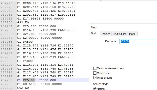
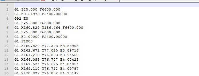
My solution: change the z-offset so that the first layer is not “smashed” and should be closer to the second layer. Oddly enough that didn’t solve anything. I set the offset to 0.2 so when the first layer is dropped it literally is dropped from 0.5mm.

This does wonders for the bed adhesion. I can finally remove my parts from the BuildTak without ripping either to shreds but the second layer keeps failing.

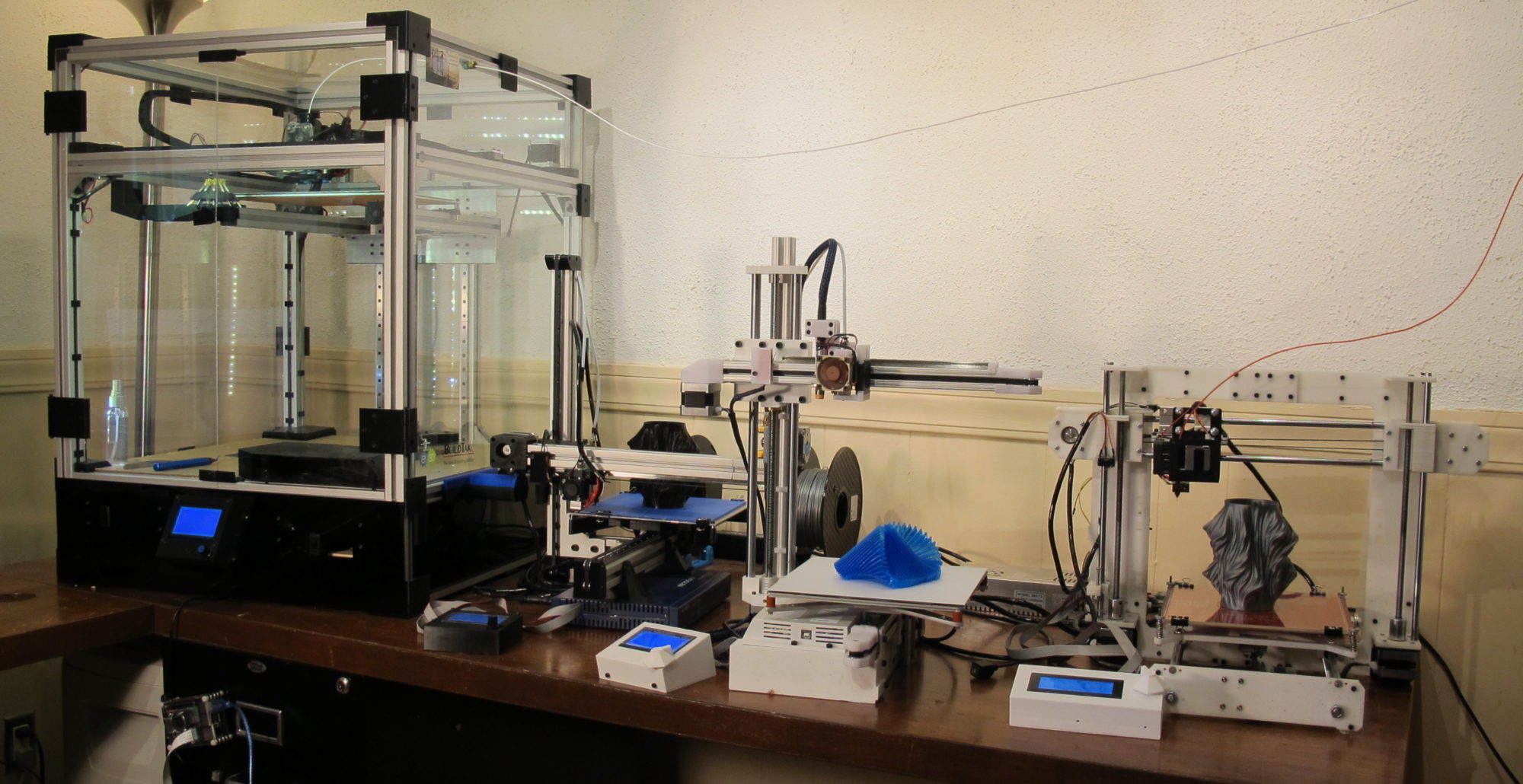
So on a quest to find the answer I started making different tests prints each with a varied parameters.

First look at different offsets:

  • 0.2mm (nozzle higher): Fail
  • 0.1mm: fail
  • 0mm: fail

Next I started looking at temperatures:

  • 245/245: fail
  • 235/235: fail
  • 235/230: fail
  • 265/265: fail

Up or down, it didn’t really matter. The problem persisted. But, as my samples started adding up, I did some measurements and the first layer of each of my print landed around 0.4mm.

I do not know why, I’m pretty sure my Z-axis is calibrating well but that made me rethink the offset again. What if I went the other way. Reduce the distance between nozzle and bed and the first layer should change in thickness. So changing the offset again:

  • -0.1mm: fail but is set in a little later
  • -0.15mm: improvement
  • -0.2mm: better

One little problem, as I keep getting closer to the bed it becomes harder to remove the print. PETG has a tendency to “fuse” to the Builtak. I learned this the hard way with my first prints on my Buildtak that ripped a hole trying to remove one of my pieces.

So what if I lower the extrusion of the first layer. That should make for less pressure. So the next parameter was the Print Settings: Advanced: First Layer. It was currently at 200%. Peculiarly high, but I’m working towards that.

down to

110%: Not much change to the second layer but a pattern appeared on the first layer. Something I’ve struggled with before and managed to fix by upping the First Layer extrusion width.

100%: Fail. This time the first layer showed the same warping as seen on the second layer prior. 

And this is when a light bulb went off. If setting the Extrusion width for the first layer to 200% fixed it’s issue, why not do the same for the Solid layers (The ones that fail).

Bingo, With Print Settings:Advanced:Solid set to 190% the problem seemed fixed.

So, unfortunately I don’t have an answer for why when slicing with Slic3r I need to set both First Layer width and Solid Layer width, as high as I have to. It does explain why it happens with Slic3r and not Cura as each tool deals with line width entirely differently.

The latest print did a great first line and a great second line. I’ve been able to back up from the plate a bit making removal from BuildTak much easier.

Let me know if you have any ideas or luck with this solution.


Continue a failed print

If you searched for “how to continue a failed print”, you probably recognize this image.

It’s the bottom part of a print  left exposed after the Titan extruder ground the filament and it no longer fed  (shame on you e3D, this never happened with my MK8).

In prior occurrences I’ve tried to tighten the knob where it is now to the point, it can’t go no more.

The head is not clogged, if I take out the ground filament, re-feed it and  tell it to extrude, it does. So today instead of starting over, I tried something different, I attempted to continue the failed print.

Here is how I did it.

I first took a very close look at the print on the board:

Step 1: Find a reference point from which you can count the layers printed. For example in the image below I can easily count the layers based on the circled reference point.

in the print I can see 4 layers printed above the end of the curve.

Step 2: Open Slic3r or whatever tool you used to slice the object and make sure you have the same settings (layer hight most importantly). If the object was scaled before make sure it is scaled the same.

Also take note of any offset used against the z axis. In my case that happened to be -0.2 which means my print started the first layer at Z0.0

Step 3: Open the preview and go to the layer you’ve identified as the last layer in the print.

Slic3r now tells me that the print ended extruding at 24.80 mm

Step 4: open the original gcode file used in the failed print (make a copy if you want to keep the original.

At this point thing can get a little tricky. Each printer uses its own g-code meta information, that may or may not be required for your print to continue.

This for example is my initial g-code:

M190 S110 ; set bed temperature and wait for it to be reached
G1 Z15 F5000 ; lift Z to avoid clamps
G28 XY
M109 T0 S215; pre heat so it can drop filament prior to moving to corner bed.
G28; home 
G29; auto level

G1 Z5 F2000 ; lift nozzle

G21 ; set units to millimeters
G90 ; use absolute coordinates
M82 ; use absolute distances for extrusion

For some of you, some of  this code needs to remain. Some MUST GO.

Doing an automatic home (G28) will probably hit your failed print in place. In my case my Z-home is done at the center of the plate. CAN’T DO THAT.

The unit/coordinate g-code may have to remain (Seemed not necessary for my printer).

In the g-code file search for the z coordinate where your print dropped its last successful line.

in this same that would be 25 (24.80 plus 0.2 for layer height).

Step 5: remove all executed g-code. In my case I removed ALL g-code prior to this line.

adapted gcode

Step 6: depending on what is left as your header g-code. you may have to set temperatures and perform homing.

Instead of leaving this “header” g-code in place I used Pronterface to do the -heating, the X and Y homing and I had to do a manual z-homing by putting the bed up to the nozzle and setting z0 (G92 Z0).

Step 7: Once temperature is set and homing is done, make sure your nozzle is position HIGHER than the last layer on your print. Depending on your printer, it may hit the print in place while positioning to its starting point otherwise.

At this point you can start your print based on the newly save g-code file.

Conclusion

Is this solution perfect? NO, it’s a hack, but in cases of prototyping where your more interested in shape than print quality, this will do in many cases.

For those of you having payed close attention, I made a mistake in mine. I restarted the print at Z 25 When I should have set it to start at 24.8 as my z-offset was -0.2 and thus layer 1 started at Z 0.

I solved this by adjusting the screws around the bed. It did the trick. below are images of the print after restart and the end result. You can clearly see the line where the print was picked up but again, In this case I wanted a finished piece and quality wasn’t the highest priority.

Continued print after updating gcode file

So there you have it. Instead of restarting a 7 hour print that was 5 hours in I managed to alter the code and restart the print (which took me about 30 minutes).

Saved myself some time and material

Upgrading the Core3D extruder assembly

When I built my first 3D printer which was based on the Prusa I3, I went with MK7 extruder clone from Aliexpress and it worked great. Great to my standards (at the time) that is. It is no longer available so when I designed the Core3D printer, I went with the MK8 extruder found on the same site. The dimensions are pretty much the same as those for the MK7.

MK8 design and issues with it.

I designed the extruder to be “suspended” underneath the extruder assembly. I went for mounting it under because the MK8 has the stepper motor mounted behind the actual extruder.  The design in Fusion 360 below shows the MK7 extruder as I never updated it to MK8. The specs remain the same though.

original MK7 extruder design for Core3D

Here is the actual implementation of the full extruder assembly.

A few things have bothered me with this design and implementation.

-Top to bottom the entire setup is 120 mm (4.72″) which is too much, the space below the X-axis used would make for close to 70 mm more build space (along the Z-axis).

-The use of aluminum and the shear size of the assembly, make it weigh close to 825 grams. Too much weight (in my opinion) to be accelerating/jerking around.

-The MK8 is a knock-off. A $1,200 printer (parts only) deserves better. I keep hearing how much better the E3d extruders are, compared to the knock-offs.

-Lots of issues loading new filament. The space between the top and the heater nozzle have too much room allowing for the filament to miss the hole.

Redesign with E3D titan extruder and hotend

Following are a few of things I wanted to achieve with the redesign:

  • Lower the height of the extruder assembly.
  • Lower the weight of the the assembly.
  • Possibly lower the width allowing for more motion along the X-axis
  • Achieve higher quality of prints.

Lowering the height

The E3D titan extruder (direct) has much more room between the stepper motor and actual hot end (Compared tot the MK8). The image below shows both extruder designs. Notice how the new Titan Extruder is much higher in height but what matters is the distance between Stepper and hot-end.

For the MK8, the distance between the bottom of the extruder and bottom of nozzle is about 25 mm.

For the Titan Extuder, this is closer to 46 mm. The difference means that I can mount the stepper motor/extruder above the X-axis rail and let the hot-end bridge the distance to below the rail.

The following image shows the true gains in Z-axis space when I place the two extuders in relationship to the X-axis rail they are riding on.

By “wrapping” the extruder around the rail, I gain about 45 mm more Z-axis to print at.

Interestingly, my bed wasn’t designed to go that high originally. It turns out the cable drag chain wasn’t put in place with that much height in mind. I had to remove some shackles to accommodate the extra gained space.

lack of room for wire drag chain

Lowering weight of Extruder Assembly

Here is the break down of what my old extruder assembly weighs:

Top Plate: 41 gr
Bottom plate: 41 gr
extruder bracket: 80 gr
plastic: 80 gr
belt clips:  11 gr
bolts/nut:  18 gr
Stepper: 280 gr
extruder:  96 gr
Hot end: 74 gr
Slider:  32 gr
cooling fan: 13 gr
fan duct:  11 gr
Inductive Sensor: 46 gr

Total:  823 gram

The numbers for the new extruder are as follows:

Top Plate: Gone
Bottom plate: Gone
extruder bracket: Gone
plastic: 27 gr
belt clips:  8 gr
bolts/nut:  8 gr
Stepper: 127 gr
extruder:  60 gr
Hot end: 44 gr
Slider:  32 gr
cooling fan: 16 gr
fan duct:  11 gr
Inductive Sensor: 46 gr

Total:  386 gram

By far the heaviest component is the stepper motor and since the Titan extruder has a 3:1 gear reduction, I can get away with a pancake stepper motor. This reduces the weight be an additional 140 grams.

New weight would come down to 386 grams

Bigger impact on rest of CoreXY

The nature of the Titan’s extruder allows me to “wrap” the entire extruder assembly around the X-axis rail. This “Wrapping will gain me close to 50 mm of additional Z-axis range.

All belts in the former Core3D design run over the X-axis as follows:

belt running atop the X-axis

in the new design the stepper motor mounted behind the extruder glides fairly closely to the rail so no more room for the belts.

The new extruder assembly required a new belt configuration. In the new implementation all belts will run underneath X-axis and inside the extrusion frame.

new belt placement below the x-axis rail

The most notable difference are:

Both X/Y stepper motors now have been turned upside down (had to figure out the firmware on that one).

The X-axis end-stop has been moved on top of the rail (in a adjustable slider)

New X Endstop on top of rail

The idlers opposite of the steppers have been placed on a single axis below/inside of extrusion frame.

Idlers before
Idlers after

A minor concern with this design is the idlers being held in place by an ABS printed corner bracket. The actual layers holding the idlers aren’t very thick. Since the belts are kept pretty tight, I wonder if this will break (it hasn’t yet).

When all is said and done

The new design has been up and running for a week now and I’m happy with the results. The new extruder operates as expected. The first 3D Benchy came out great.

This is what the new setup looks like:

New Core XY with E3d Titan Extuder

Here it is at work: