Since I’ve not futzed around with this issue for the last 12 hours, I’m thinking it maybe worth writing it up.
I’ve started printing with PETG recently as I’m getting sick and tired (sick from the smell, tired from the warping) printing ABS. PETG is a good alternative to
ABS as it has the best of PLA and ABS (no smell/no warping with some of the ABS strength and temperature tolerance).
I’ve tried different brands (Total Pack/HatchBox and now eSun). All three create the same phenomenon as seen above. Strange warping of the second layer.
One sure way of solving it: While the print is going move the bed one quarter turn of the bed screws closer to the head.
What Does that tell me. Well it seems like the nozzle is to far from the last printed layer.
Note: this happens in Slic3r and not with Cura, but Cura is giving me other headaches so I want this to work with Slic3r.
My solution: change the z-offset so that the first layer is not “smashed” and should be closer to the second layer. Oddly enough that didn’t solve anything. I set the offset to 0.2 so when the first layer is dropped it literally is dropped from 0.5mm.
This does wonders for the bed adhesion. I can finally remove my parts from the BuildTak without ripping either to shreds but the second layer keeps failing.
So on a quest to find the answer I started making different tests prints each with a varied parameters.
First look at different offsets:
0.2mm (nozzle higher): Fail
0.1mm: fail
0mm: fail
Next I started looking at temperatures:
245/245: fail
235/235: fail
235/230: fail
265/265: fail
Up or down, it didn’t really matter. The problem persisted. But, as my samples started adding up, I did some measurements and the first layer of each of my print landed around 0.4mm.
I do not know why, I’m pretty sure my Z-axis is calibrating well but that made me rethink the offset again. What if I went the other way. Reduce the distance between nozzle and bed and the first layer should change in thickness. So changing the offset again:
-0.1mm: fail but is set in a little later
-0.15mm: improvement
-0.2mm: better
One little problem, as I keep getting closer to the bed it becomes harder to remove the print. PETG has a tendency to “fuse” to the Builtak. I learned this the hard way with my first prints on my Buildtak that ripped a hole trying to remove one of my pieces.
So what if I lower the extrusion of the first layer. That should make for less pressure. So the next parameter was the Print Settings: Advanced: First Layer. It was currently at 200%. Peculiarly high, but I’m working towards that.
down to
110%: Not much change to the second layer but a pattern appeared on the first layer. Something I’ve struggled with before and managed to fix by upping the First Layer extrusion width.
100%: Fail. This time the first layer showed the same warping as seen on the second layer prior.
And this is when a light bulb went off. If setting the Extrusion width for the first layer to 200% fixed it’s issue, why not do the same for the Solid layers (The ones that fail).
Bingo, With Print Settings:Advanced:Solid set to 190% the problem seemed fixed.
So, unfortunately I don’t have an answer for why when slicing with Slic3r I need to set both First Layer width and Solid Layer width, as high as I have to. It does explain why it happens with Slic3r and not Cura as each tool deals with line width entirely differently.
The latest print did a great first line and a great second line. I’ve been able to back up from the plate a bit making removal from BuildTak much easier.
Let me know if you have any ideas or luck with this solution.
Important Update: In order for this to work you need to install the Marlin bugfix-1.1.x.zip version of Marlin. The current release has some serious issues (travel distances are all out of wack).
Spoiler alert, this is what the upgrade did for my printer:
Introduction
Tired of the constant noise your printer is making. Upgrading your RAMPS 1.4 (or most any AT Mega based controllers) with the TMC2130 stepper motors might do the trick.
In this instructable I will not go into the technical babble of PSI, Master/Slave and clock speeds. If you’re interested in that I refer you to
Also if anything in this instructable seems unclear, check with those sites. To their credit, I’ve used them mainly as the source for my upgrade.
Here are some of the advantages I’ve been reading about:
Super quiet operation
Ability to configure via software
Proper alignment of controller which allows for proper cooling of the driver chips
Possibility of homing X and Y without End stops (diagnosis allows for the software to recognize the axis bumping into things). (this in a later instructable)
Potentially with future updates of Marlin the ability to act on missed steps during printing (like Prusa I3 MK3 can do today).
What it boils down to is that these new stepper drivers can be controlled via software and can run in an ultra silents mode (with 256 micro steps). With these new stepper drivers you no longer need to adjust the little pot meters on the driver but instead can tell it via g-codes at how many amps/volts to run.
When buying these steppers online be cautious about how they are delivered. Most of them (on amazon.com) already have all pins soldered to them which is a problem as 4 of the pins are pointing the wrong way.
I’ve ordered the steppers directly from the US distributor (Filastruder.com) and they come with pins but not soldered on.
In this instructable I will start with the bear stepper driver, solder the pins and create a wiring harness that connects all the right pins on the steppers to the proper pins on the RAMPS 1.4 board.
This instructable will be for the RAMPS 1.4 board but many derivatives use the exact same pin configurations (I will try this out on my KFB 2.0 board).
Things you need
The following items are pre-requisite to this project:
In this project I’m replacing all 4 drivers but you could just replace X and Y as they do most of the work
Ramps 1.4 Board (or RAMPS 1.4 Compatible): (if you buy a kit will will get the A4988 drivers that you will be replacing but the price might still be right): $29.99 http://amzn.to/2FqmN51
The TMC2130 drivers come un-assembled so first we need to prepare each stepper putting the all the pins in the right places.
Very important about steppers. Trinamic seems to be the only company to do it right. Adding the usual heatsinks on top of a chip is a bit of joke as heat travels below the chip through the board. These little boards are build such that the chip will be underneath the board when assembled and the heat sink can be applied on top of the board.
For this project I added the 4 PSI pins as well as the end stop pin (for end-stop-less homing).
I cut the strips of pins in the right size for assebly (row of 8 pointing down), 4 PSI up, 1 Diagnostic up, one down (En) and 2 down (Dir, Step)
First I will solder the top pins to the driver (I’m using a piece of double sided PCB board to place and rest the pins).
Next I place the bottom pins in place on the PCB board and lay the driver on top and solder the downward facing pins.
Once all pins are soldered simply rinse and repeat for the remaining chips.
Before putting the drivers in your RAMPS 1.4 please note that you can remove the three jumpers that used to set your stepping to 1/16th. It is now handled by the software. I removed mine but I’ve read you may leave them as they no longer are connected to anything (probably did something to the pins that are now pointing up).
Step 3: Wiring With AUX 3 Available
The common setup TMC2130 setup for marlin assumes that the both Aux 2 and Aux 3 on the RAMPS board are available (like the first image of this step). If your are using a LCD with SD Card adapter, Aux 3 is not available and wiring for that situation will be discussed in the next Step.
The wiring image shows how all wires go to the 2 Aux clusters. Also note that three of the 4 wires are all combined and end up on 1 pin on Aux 3
SDI for X/YZ/E0 all go to pin D51
SCK for X/YZ/E0 all go to pin D52
SDO for X/YZ/E0 all go to pin D50
CS for X goes to D53
CS for Y goes to D49
CS for Z goes to D40
CS for E0 goes to D42
For my project I created a wiring harness that consists of 4 repurposed Stepper wires.
I solder and combined all Black wires into one single black wire ending up with a female connector for a single pin
I solder and combined all Green wires into one single black wire ending up with a female connector for a single pin
I solder and combined all Blue wires into one single black wire ending up with a female connector for a single pin
The Red wires each end up with their own single female pin connector as they each have their own pins assigned on Aux.
Step 4: Wiring With LCD Installed (Aux 3 Not Available)
Okay, so browsing around the web I can’t find a real clean solution to this. It’s not that hard to reroute X CS and Y CS to other ports but the RAMPS 1.4 only seems to have one SCK and the two MISO pins which are used by the Card Reader on the LCD Unit.
The solution I’ve come up with for now is to extend the LCD connector with three pins on top. It’s not pretty but it seems pretty sturdy (if soldered well). If you screw it up a new adapter only costs a few dollars on Amazon.com (http://amzn.to/2oNVPdM).
In order to reroute the CS pins, you’ll need to update the pin_RAMPS.h file
Redirecting these pins works but I’m a bit concerned about some of the threads I’m reading on using the SD card in combination with the TMC2130 (now sharing the same pins as the SD Reader). I will have to runs some more testing once all installed.
The new schematic images will show the new wiring configurations. Just follow the lines.
Setting Up the Software
Once all the hardware is connected (in fairness, I did one Stepper at a time) you will need to make the software aware of the new Drivers. If you are rerouting some of the CS pins because you’re using an LCD (adapter) you’ve already made some changes to the pins_RAMPS.h file but for normal operation most changes occur in the Configuration_adv.h
If you have the latest (or a newer version) of Marlin (I’m using 1.1.8 as of this writing) you can open the configuration_adv.h and search for TMC2130. It will take you right to the TMC2130 section.
First thing you do is uncomment (remove // from in front of) #define HAVE_TMC2130
// @section TMC2130, TMC2208/**
 * Enable this for SilentStepStick Trinamic TMC2130 SPI-configurable stepper drivers.
 *
 * You'll also need the TMC2130Stepper Arduino library
 * (https://github.com/teemuatlut/TMC2130Stepper).
 *
 * To use TMC2130 stepper drivers in SPI mode connect your SPI2130 pins to
 * the hardware SPI interface on your board and define the required CS pins
 * in your `pins_MYBOARD.h` file. (e.g., RAMPS 1.4 uses AUX3 pins `X_CS_PIN 53`, `Y_CS_PIN 49`, etc.).
 */
#define HAVE_TMC2130
Next you un-comment those lines that represent the Stepper motors you will be controlling with the new TMC2130 drivers.
In this case I uncomment all three Axis and the Extruder (E0)
The next section when you scroll down is where you define the power setting of all and each of the divers. In may case I’m pretty much leaving these as is. The first setting R_SENSE I believe has to do with any resistance the motor meets and when to do something with it. Some speculation as I haven’t found much on it (let me know if you do)
The second setting HOLD_MULTIPLIER will lower the current by half (or what value you set it to) when the motors are idle. It reduces heat but in some cases also handle the high pitched whining of idle motors.
The third setting INTERPOLATE is what gives the magic to these new drivers so leave it set to true. I will take the 16 steps your RAMPS sends the driver and turns it into 256, giving is the silent and smooth motion.
/**
* Stepper driver settings
*/
#define R_SENSE           0.11  // R_sense resistor for SilentStepStick2130
#define HOLD_MULTIPLIER    0.5  // Scales down the holding current from run current
#define INTERPOLATE       true  // Interpolate X/Y/Z_MICROSTEPS to 256
In the following section you can set the Current and Micro Steps per motor. This is a really nice feature as you no longer have open up your electronics and mess with the little pot-meter on each driver. You can set this value in the configuration here but there’s also a way to change it on the fly with g-code M906 (M906 X900 sets the current for X to 900mA). You can play around with these values to figure out what works best for you.
The _MICROSTEPS setting is a bit confusing but, if you had 3 jumpers underneath your old driver leave it at 16, The interpolation will still bring it to 256.
The TMC2130 can run in two modes: spreadCycle of StealthChop. It’s the StealChop that’s making your printing invisible (to the ears that is). So most of you will install it for that reason. With StealthChop you also get less power and thus you can’t print as fast as you might have once wanted (personally I think speed is overrated).
In SpreadCycle Mode the drivers can run your prints faster as it can create more torque. It also get noisier though. If you’re interested in the TMC2130 for it’s lack of noise you will want to enable the StealthChop mode by uncommenting the following:
/**
* Use Trinamic's ultra quiet stepping mode.
* When disabled, Marlin will use spreadCycle stepping mode.
*/
#define STEALTHCHOP
The next setting of MONITOR_DRIVER_STATUS I’m unfamiliar with (as of yet) so I’m going to leave it commented.
Should you wish to have the best of both worlds: Quiet when possible and powerful when needed you can choose to enable the hybrid mode:
/**
   * The driver will switch to spreadCycle when stepper speed is over HYBRID_THRESHOLD.
   * This mode allows for faster movements at the expense of higher noise levels.
   * STEALTHCHOP needs to be enabled.
   * M913 X/Y/Z/E to live tune the setting
   */
  #define HYBRID_THRESHOLD  <br>
  #define X_HYBRID_THRESHOLD     98  // [mm/s]
  #define X2_HYBRID_THRESHOLD    100
  #define Y_HYBRID_THRESHOLD     98
  #define Y2_HYBRID_THRESHOLD    100
You can set the speed at which the printer should switch from one mode to the next. The long and peaceful quiet may be gone.
As of this writing I will not go into sensorless homing yet as I’m quite happy with the homing I have today.
Before uploading the software I would recommend enabling the TMC debuggging option by un-commenting TMC_DEBUG. With the m122 command you can get useful information (especially when first trying out the new steppers).
/** Enable M122 debugging command for TMC stepper drivers.
   * M122 S0/1 will enable continous reporting.
   */
  #define TMC_DEBUG
Testing the New TMC2130 Drivers
If you’re lucky like me you have enough spare parts laying around to do some testing. In this case I’m using a spare RAMPS 1.4 kit, and 4 steppers I had laying around.
I’ve inserted all four stepper drivers and hooked up the motors.
In order for you to test with RAMPS 1.4 you need to AT LEAST connect a thermistor to the TEMP0 (without Marlin does not like to operate, unless major code changes).
If you want to test the extruder stepper you will also need to disable the PREVENT_COLD_EXTRUSION or change the EXTRUDE_MINTEMP to room temperature (something like 18 Celcius)
in configuration.h
// This option prevents extrusion if the temperature is below EXTRUDE_MINTEMP.<br>// It also enables the M302 command to set the minimum extrusion temperature
// or to allow moving the extruder regardless of the hotend temperature.
// *** IT IS HIGHLY RECOMMENDED TO LEAVE THIS OPTION ENABLED! ***
//#define PREVENT_COLD_EXTRUSION
//#define EXTRUDE_MINTEMP 170
Hook up your RAMPS to a 12 Volt source (powerful enough to run the steppers) and upload your Marlin to the test board.
You can now connect to the board via USB with a program like Pronterface and test some things.
First off run the M122 command which, if you enabled the TMC_DEBUG (in previous step) will provide a bunch of information on the stepper drivers.
The following is a dump of the information of my drivers.
>>> m122
SENDING:M122
		X	Y	Z	E0
Enabled		false	false	false	false
Set current	800	800	800	800
RMS current	795	795	795	795
MAX current	1121	1121	1121	1121
Run current	25/31	25/31	25/31	25/31
Hold current	12/31	12/31	12/31	12/31
CS actual		12/31	12/31	12/31	12/31
PWM scale	128	128	40	39
vsense		1=.18	1=.18	1=.18	1=.18
stealthChop	true	true	true	true
msteps		16	16	16	16
tstep		1048575	1048575	1048575	1048575
pwm
threshold		0	0	0	0
[mm/s]		-	-	-	-
OT prewarn	false	false	false	false
OT prewarn has
been triggered	false	false	false	false
off time		5	5	5	5
blank time	24	24	24	24
hysterisis
-end		2	2	2	2
-start		3	3	3	3
Stallguard thrs	0	0	0	0
DRVSTATUS	X	Y	Z	E0
stallguard
sg_result		0	0	0	0
fsactive
stst		X	X	X	X
olb		X	X
ola		X	X
s2gb
s2ga
otpw
ot
Driver registers:
	X = 0xE0:0C:00:00
	Y = 0xE0:0C:00:00
	Z = 0x80:0C:00:00
	E0 = 0x80:0C:00:00
I’m not going to bore you with too much details (Still have to figure out a bunch myself) but if in the Driver registers at the bottom you see 0xFF… it means something is not connector properly for that stepper driver.
You can now start sending commands to the motors and see if they are running properly. in the video below you hear the Case fan of my CoreXY Printer (next project). The motors themselves, I cannot hear.
Conclusion
The installation of the new TMC2130 seems more daunting than it is. Yes, you will need to do some soldering, there are more wires than ever before but I can’t wait to install these permanently into my CoreXY printer. Once I have I will post the before and after video (and most importantly the audio).
Let me know what I got wrong, I’m here to learn myself. If you’re eager to learn more about the sensorless homing, please support me on Patreon.com. I will need to purchase a new set of Drivers for that one.
When I built my first 3D printer which was based on the Prusa I3, I went with MK7 extruder clone from Aliexpress and it worked great. Great to my standards (at the time) that is. It is no longer available so when I designed the Core3D printer, I went with the MK8 extruder found on the same site. The dimensions are pretty much the same as those for the MK7.
MK8 design and issues with it.
I designed the extruder to be “suspended” underneath the extruder assembly. I went for mounting it under because the MK8 has the stepper motor mounted behind the actual extruder. The design in Fusion 360 below shows the MK7 extruder as I never updated it to MK8. The specs remain the same though.
original MK7 extruder design for Core3D
Here is the actual implementation of the full extruder assembly.
A few things have bothered me with this design and implementation.
-Top to bottom the entire setup is 120 mm (4.72″) which is too much, the space below the X-axis used would make for close to 70 mm more build space (along the Z-axis).
-The use of aluminum and the shear size of the assembly, make it weigh close to 825 grams. Too much weight (in my opinion) to be accelerating/jerking around.
-The MK8 is a knock-off. A $1,200 printer (parts only) deserves better. I keep hearing how much better the E3d extruders are, compared to the knock-offs.
-Lots of issues loading new filament. The space between the top and the heater nozzle have too much room allowing for the filament to miss the hole.
Redesign with E3D titan extruder and hotend
Following are a few of things I wanted to achieve with the redesign:
Lower the height of the extruder assembly.
Lower the weight of the the assembly.
Possibly lower the width allowing for more motion along the X-axis
Achieve higher quality of prints.
Lowering the height
The E3D titan extruder (direct) has much more room between the stepper motor and actual hot end (Compared tot the MK8). The image below shows both extruder designs. Notice how the new Titan Extruder is much higher in height but what matters is the distance between Stepper and hot-end.
For the MK8, the distance between the bottom of the extruder and bottom of nozzle is about 25 mm.
For the Titan Extuder, this is closer to 46 mm. The difference means that I can mount the stepper motor/extruder above the X-axis rail and let the hot-end bridge the distance to below the rail.
The following image shows the true gains in Z-axis space when I place the two extuders in relationship to the X-axis rail they are riding on.
By “wrapping” the extruder around the rail, I gain about 45 mm more Z-axis to print at.
Interestingly, my bed wasn’t designed to go that high originally. It turns out the cable drag chain wasn’t put in place with that much height in mind. I had to remove some shackles to accommodate the extra gained space.
lack of room for wire drag chain
Lowering weight of Extruder Assembly
Here is the break down of what my old extruder assembly weighs:
Top Plate: 41 gr Bottom plate: 41 gr extruder bracket: 80 gr plastic: 80 gr belt clips: 11 gr bolts/nut: 18 gr Stepper: 280 gr extruder: 96 gr Hot end: 74 gr Slider: 32 gr cooling fan: 13 gr fan duct: 11 gr Inductive Sensor: 46 gr
Total: 823 gram
The numbers for the new extruder are as follows:
Top Plate: Gone Bottom plate: Gone extruder bracket: Gone plastic: 27 gr belt clips: 8 gr bolts/nut: 8 gr Stepper: 127 gr extruder: 60 gr Hot end: 44 gr Slider: 32 gr cooling fan: 16 gr fan duct: 11 gr Inductive Sensor: 46 gr
Total: 386 gram
By far the heaviest component is the stepper motor and since the Titan extruder has a 3:1 gear reduction, I can get away with a pancake stepper motor. This reduces the weight be an additional 140 grams.
New weight would come down to 386 grams
Bigger impact on rest of CoreXY
The nature of the Titan’s extruder allows me to “wrap” the entire extruder assembly around the X-axis rail. This “Wrapping will gain me close to 50 mm of additional Z-axis range.
All belts in the former Core3D design run over the X-axis as follows:
belt running atop the X-axis
in the new design the stepper motor mounted behind the extruder glides fairly closely to the rail so no more room for the belts.
The new extruder assembly required a new belt configuration. In the new implementation all belts will run underneath X-axis and inside the extrusion frame.
new belt placement below the x-axis rail
The most notable difference are:
Both X/Y stepper motors now have been turned upside down (had to figure out the firmware on that one).
The X-axis end-stop has been moved on top of the rail (in a adjustable slider)
New X Endstop on top of rail
The idlers opposite of the steppers have been placed on a single axis below/inside of extrusion frame.
Idlers beforeIdlers after
A minor concern with this design is the idlers being held in place by an ABS printed corner bracket. The actual layers holding the idlers aren’t very thick. Since the belts are kept pretty tight, I wonder if this will break (it hasn’t yet).
When all is said and done
The new design has been up and running for a week now and I’m happy with the results. The new extruder operates as expected. The first 3D Benchy came out great.
After reading this, please consider supporting me at GoFundMe
The Core3D printerwas implemented using CoreXY as its method of motion. When I first learned about it, it reminded me of my etch a sketch. I realize, not the best founded reason for approaching something new.
The other most common methods are Delta and Cartesian. Not sure Cartesian is the right name for one of them as all methods apply to X, Y and Z coordinates. I don’t don’t René Descartes had in mind how motors would operate to reach X=0, Y=0 and Z=0.
Let look a bit closer at all three methods.
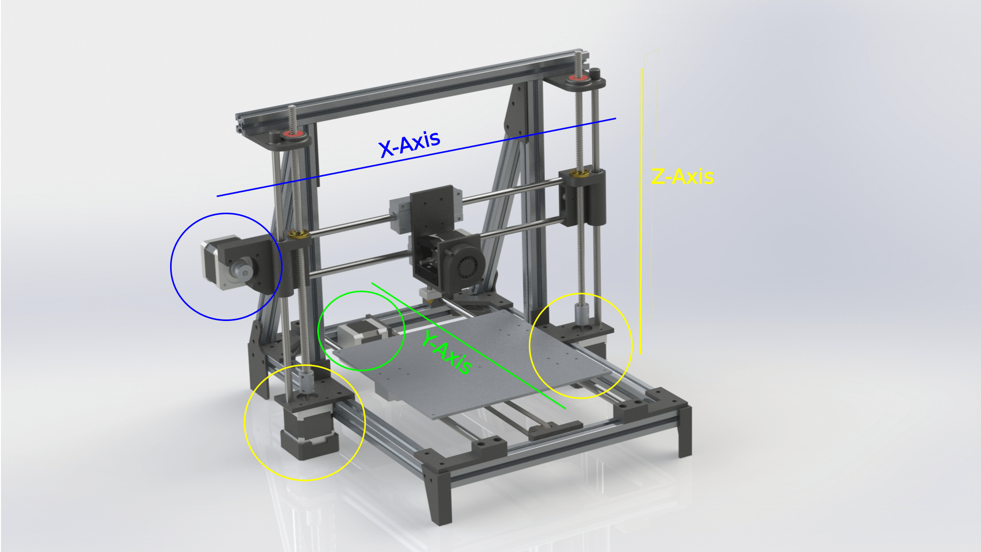
Cartesian
The most common method in the world of 3D Printing is referred to as Cartesian motion. An example of this would be the Original RapRap implementation. Each axis has it’s own dedicated stepper motor(s). One for the X-Axis which travels up and down along the Z-axis. One Stepper motor for the Y-Axis which in case of the Prusa pulls the bed back and forth and 1 or 2 stepper motors for the Z-Axis which in this case lifts the entire X-Axis.
This method is the default implementation for the Marlin Firmware which operates a large portion of the 3D printer world.
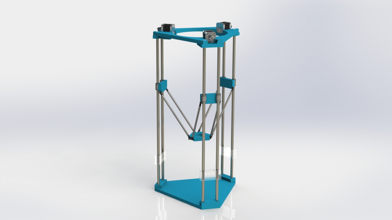
Delta
The Delta 3D printer uses a completely different mechanism. The extruder head is controlled by 3 arms that move up and down their own (parallel) rails. The software calculates the proper movement to come to X, Y and Z coordinates.
In the printer above three stepper motors all move in parallel but independently (up and down). The Delta printer is probably the second most available printer. From what I’ve read, trouble shooting is not as straight forward as the motion is is much less intuitive than the standard “Cartesian” motion.
Core XY
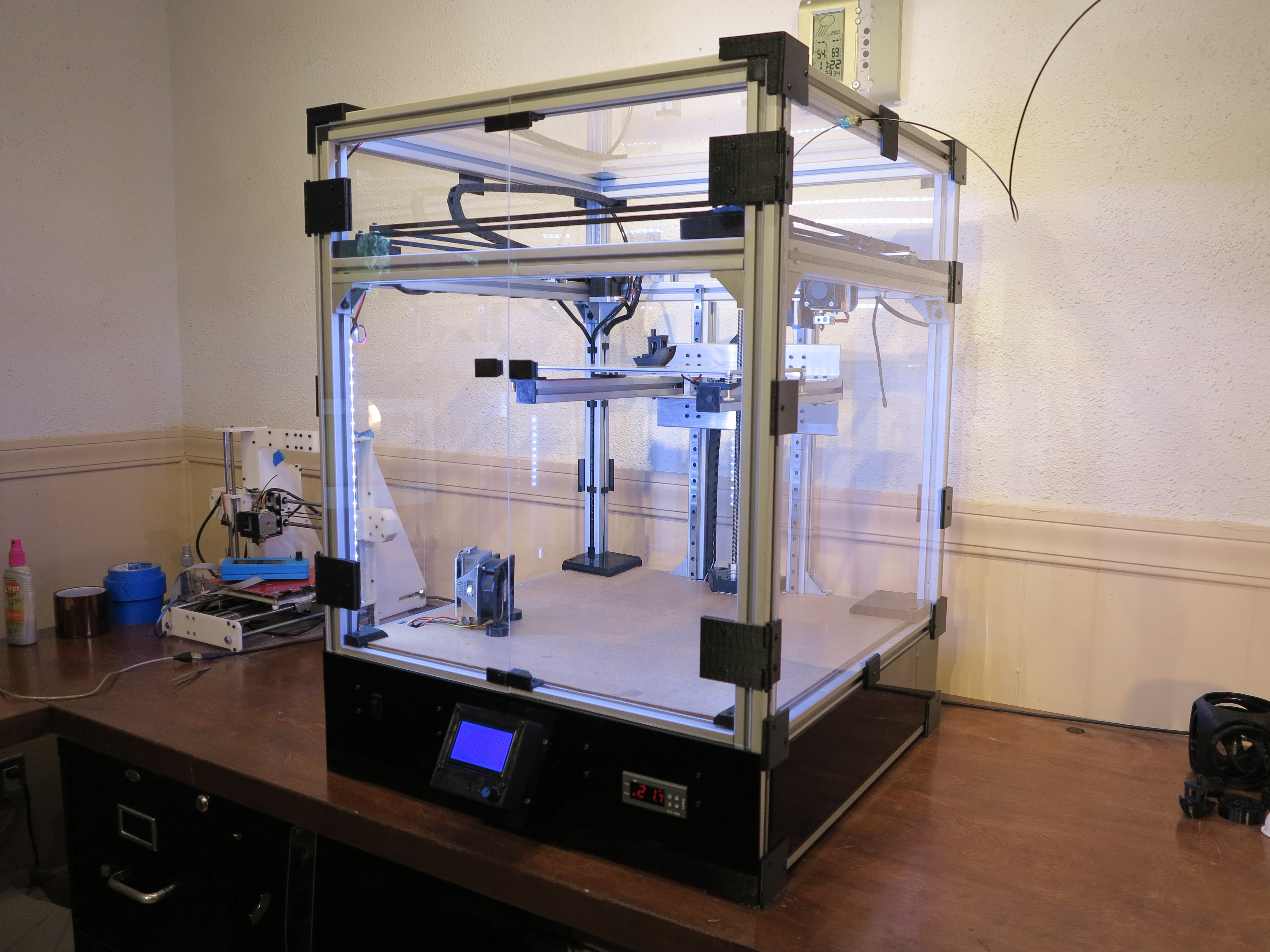
Less common, although seemingly on the rise is the Core XY motion. The best way to explain Core XY is to refer to coreXY.com but lets use the Core3d printer as a reference here.
Core3D Printer CoreXY design
X and Y are controlled by two stationary stepper motors. Neither motor is dedicated to a single axis, instead the firmware will use the motors in tandem to reach the different X and Y coordinates.
Don’t worry about the math: Marlin Firmware takes care of all of this but in case you’re interested:
In the case of the Core3D printer, the Z-axis is controller by a single stepper moving the bed up and down.
Core3D printer X/Y/Z assembly using CoreXY
The nice thing about all these mechanisms of motion is that you don’t have to figure it out. CoreXY is much less intuitive than the normal “Cartesian” but as far as I’m concerned it is just a configuration in the Marlin software. I’ll write a more detailed post on the configuration.
So why Core XY for the Core3D printer?
I’ll be real honest here, I could have gone with ordinary Cartesian like the Prusa but why settle for ordinary? My primary goal was to create an enclosed printer with lots of bells and whistles.
The anecdotal word on CoreXY is that:
it is more accurate. The fact that both stepper motors are stationary adds to that accuracy . In most 3D printers, one stepper motor moves the entire bed (which, with high builds and high speed, can introduce wobble). In the Cartesian implementation, the motor controlling the X-axis moves up and down with the Z-Axis (be it very small increments each layer) and the Z-axis lifts the entire X-axis installation. It is important to note that this accuracy depends a lot on the weight of the extruder assembly and sturdiness of the frame it sits in.
It can operate faster. Yes, I can run the head back and forth at 10,000 mm/sec but that doesn’t make it accurate. As a matter of fact, I don’t think extruders can even handle that type of speed.
The bed doesn’t move along the Y-axis (stationairy on delta as well) so that makes for more stability. In General the bed moving around isn’t that much of an issue as long as it is light enough. When you move to metal bed, not to mention bigger prints, weight can start becoming an issue moving back and forth that fast.
I have a feeling, proponents of the other types of motion will argue or put forth similar points to defend their methods. I’m tempted to create a second version of my printer and have it implement the Cartesian motion for X and Y (I would leave the Z-Axis as is).
I thought about doing something with delta but I was put off by some of the comments around difficulty with troubleshooting. It also feels to me like the 3 spindly arms can’t withstand much force.
I went with CoreXY as, personally, I think it’s more elegant. It’s not forced to move clunky (in some cases) heavy stepper motors and extruders around. That said, the Core3D printer can actually use some improvement there, as the current construction of the extruder/brackets/inducer still ended up quite heavy.
Current Core3D extruder assembly
One of my next updates will be that of reducing the size and weight of the extruder assembly.


