
A quick tutorial on how to connect a BLTOUCH to KFB2.0. The reason this is slightly different from other boards is because KFB2.0 is missing dedicated Servo pins.
In order to figure this out I ordered a genuine BLTOUCH from Amazon, so if you’re using a clone, this should probably still work but no guarantees.
The BLTOUCH consists of 2 sets of wires. The end stop wires and the servo wires.
The end stop wires will go into the regular end stop connectors but for the servo wires we need to use an alternative to get around the missing servo pins
There are many parts required to wire up a KFB2.0 but for this instructable you will need at least

BLTOUCH Amazon $37.98 (no extended wires, get extended if you need them)

For this setup we’re going to use/abuse the Z-Max end stop connector to run the servo on the BLTOUCH
Z-Min is used as the actual end stop

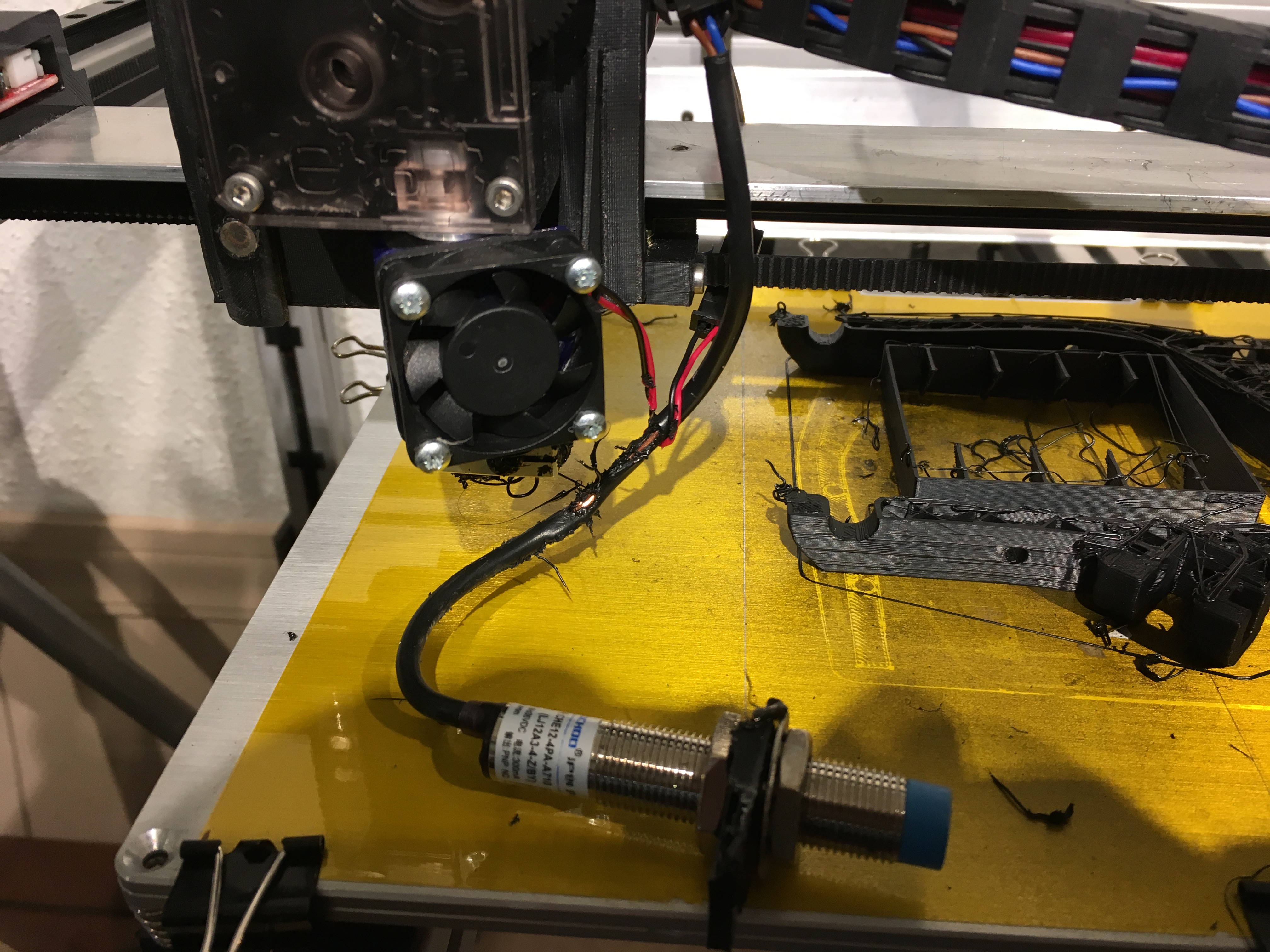
The picture says it all. Connect all 5 wires from your BLTOUCH according to the image with the Servo wires being handled by the Z-Max connector.
In the software setup we’ll redirect the pins
A few changes have to be made to enable the BLTOUCH and redirect the pins
In Configuration.h
Pick the MKS_GEN_L board for the KFB2.0
#ifndef MOTHERBOARD<br>  #define MOTHERBOARD BOARD_MKS_GEN_L
#endif
Practically all of the following settings are a matter of uncommenting/commenting your code by adding/removing // (adding these will disable code)
For this setup it is assumed you will be using the Z-Min for the Z endstop
#define USE_XMIN_PLUG<br>#define USE_YMIN_PLUG
#define USE_ZMIN_PLUG
define your ENDSTOPPULLUPs, make sure it uses ENDSTOPPULLUP_ZMIN_PROBE
#define ENDSTOPPULLUPS<br>#if DISABLED(ENDSTOPPULLUPS)
  // Disable ENDSTOPPULLUPS to set pullups individually
  //#define ENDSTOPPULLUP_XMAX
  //#define ENDSTOPPULLUP_YMAX
  //#define ENDSTOPPULLUP_ZMAX
  #define ENDSTOPPULLUP_XMIN
  #define ENDSTOPPULLUP_YMIN
  //#define ENDSTOPPULLUP_ZMIN
  #define ENDSTOPPULLUP_ZMIN_PROBE
#endif
for my BLTOUCH installation I have the inversion set to false
#define Z_MIN_PROBE_ENDSTOP_INVERTING false // set to true to invert the logic of the probe.
let the system know it uses the probe for Z-min
#define Z_MIN_PROBE_USES_Z_MIN_ENDSTOP_PIN
turn on BLTOUCH
#define BLTOUCH
#if ENABLED(BLTOUCH)
  #define BLTOUCH_DELAY 100   // (ms) Enable and increase if needed
#endif
The following setting are going to depend on where you have mounted your BLTOUCH. Measure the distance from your BLTOUCH pin to your extruder. These values make sure you remain on top of your bed when auto leveling. The values below may (and probably won’t) match your setup
#define X_PROBE_OFFSET_FROM_EXTRUDER 48  // X offset: -left  +right  [of the nozzle]
#define Y_PROBE_OFFSET_FROM_EXTRUDER -2  // Y offset: -front +behind [the nozzle]
#define Z_PROBE_OFFSET_FROM_EXTRUDER 0   // Z offset: -below +above  [the nozzle]
set probe speed
#define XY_PROBE_SPEED 8000
IF you want the probe to do a double touch (or more)
#define MULTIPLE_PROBING 2
The following setting will position your extruder prior to during and after probing
#define Z_CLEARANCE_DEPLOY_PROBE   15 // Z Clearance for Deploy/Stow
#define Z_CLEARANCE_BETWEEN_PROBES  10 // Z Clearance between probe points
#define Z_CLEARANCE_MULTI_PROBE     5 // Z Clearance between multiple probes
//#define Z_AFTER_PROBING           5 // Z position after probing is done
Make the system aware of at least this servo
#define NUM_SERVOS 1 // Servo index starts with 0 for M280 command
#define SERVO_DELAY { 300 }
If you are going to use the BLTOUCH for Auto Bed Leveling set the next values
#define AUTO_BED_LEVELING_BILINEAR
Since the KFB 2.0 does not have its dedicated Servo pins we using the X-Max plug to power the servo that is inside the BLTOUCH.
For this we need to tell the Marlin firmware to redirect some pins.
It is assumed you have selected BOARD_MKS_GEN_L in the configuration.h
open the file pins_MKS_GEN_L.h
in it add the following Make sure you add this AFTER the line #include “pins_RAMPS.h”:
#include "pins_RAMPS.h"
//redirect the servo pin to the X-Max plug
#define SERVO0_PIN 19
If you want to test the pins with g-code m43 you’ll need to enable #define PINS_DEBUGGING in configuration_adv.h
#define PINS_DEBUGGING
Once you’ve uploaded the updated Marlin FW to the board you can test the BLTOUCH.
If your firmware is setup for Safe Z-homing (meaning you can’t home z before having homed X or Y) you either need to turn this feature off in the firmware
in configuration.h comment out Z_SAFE_HOMING
//#define Z_SAFE_HOMING
or have your X and Y end stops connected.
First test is to see what happens with you turn on/power up your board. In this setup the BLTOUCH lights up when powering on and does two servo action. The probe pin comes out twice and retracts
As far as lights is concerned I see the orange light and a small purple led on. (not quite clear in the photo)
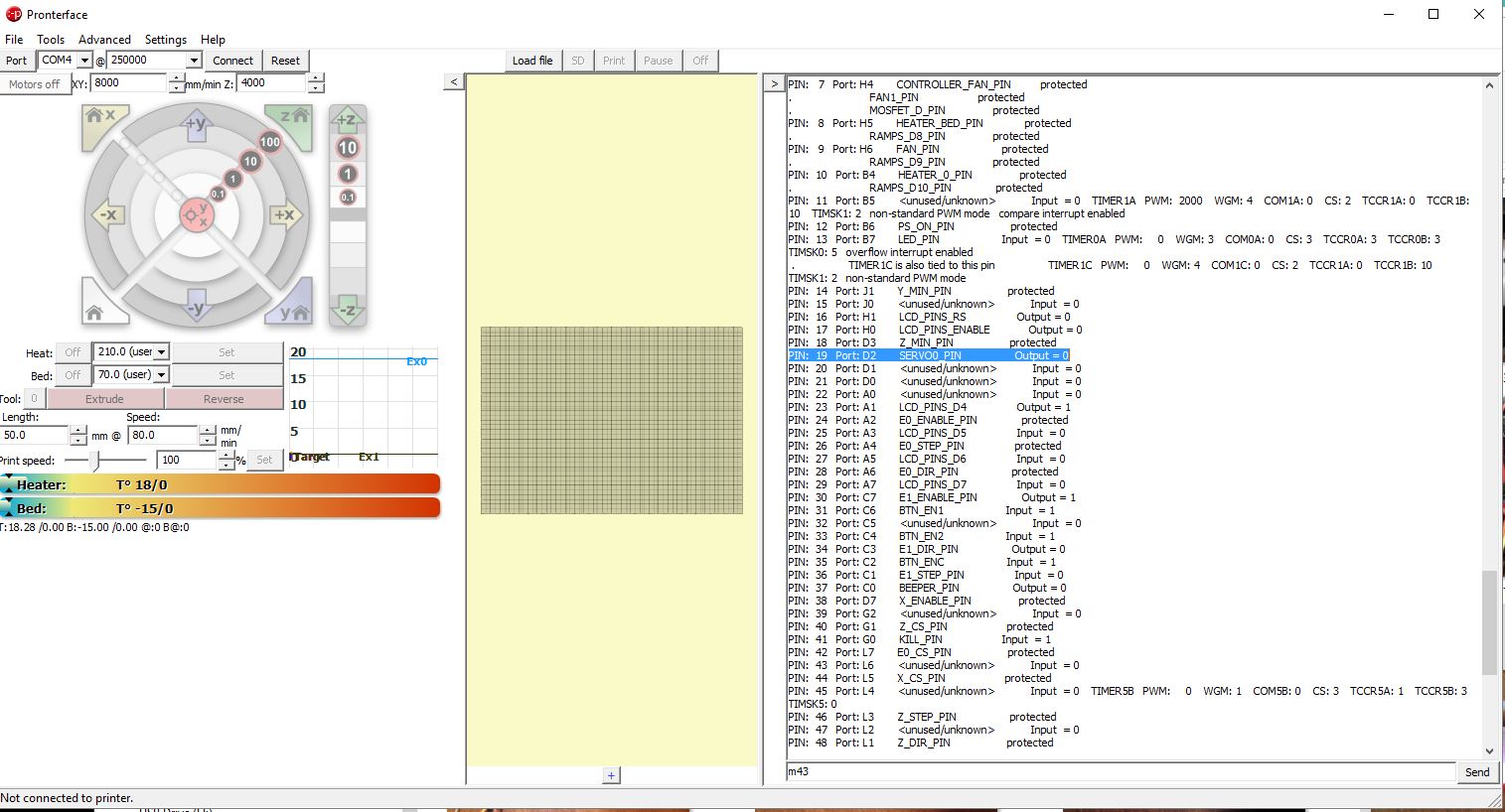
connect to the board with something like PronterFace or OCtoPrint and send it g-code m43 (if you’ve enabled PINS_DEBUGGING in the last step)
Check to see if pin 19 is indeed set to SERVO0_pin
Next check out this video for testing the BLTOUCH setup
If this was useful to you in anyway, please consider supporting me through Patreon or making a small donation here.