Lithophane Design tools by LithophaneMaker.com

Most of the items I print are functional items used to create things that do something of things that serve a purpose (mostly parts for other 3D Printers).  Yes, Baby Groot is lovely to look at but I just don’t go there. The one exception I make, is Lithophanes. As a matter of fact, I find Lithophanes make great gifts for friends, families and loved ones. They can be nonsensical or very personal. They’re generally a hit. Following is a guest post from the creators at Lithophanemaker.com.

Lithophanemaker.com was created by hobbyist 3d printer and coder, Thomas Brooks. Thomas originally made the tool to save time when generating night light lithophanes, and then decided to share the tool with the larger lithophane 3d printing community.

A popular instructables article (https://www.instructables.com/id/Lithophane-Night-Light/) highlighted six steps that someone would need to create a night light lithophane using conventional methods. The night light lithophane design tool reduces the number of steps down to two: 1) Make lithophane stl, and 2) print stl file.

As of November 2018, https://lithophanemaker.com has five tools which have saved its users approximately 800 hours of time they would have spent editing lithophanes in CAD. The five tools provide users with a simple interface for designing

  1. Curved, framed lithophanes (https://lithophanemaker.com/Curved Lithophane Designer.html)
  2. Flat framed lithophanes (https://lithophanemaker.com/DesignWindow Lithophane.html) with optional holes for twine, a tab for a hook, or only the frame,
  3. Night light lithophanes (https://lithophanemaker.com/Design Night Light.html) with easily customizable features to make them compatible with almost any night light
  4. A lamp lithophane design tool (https://lithophanemaker.com/Lamp Lithophane Designer.html) that interfaces with lamps you already own, and finally 5) a circular lithophane (https://lithophanemaker.com/Design Lithophane Tag.html) design tool that can make Christmas ornaments, a necklace charm, or a tag for a pet’s collar.

These tools are made freely available to anyone! If you have any suggestions for ways to improve the tools please contact Thomas Brooks as support@lithophanemaker.com

Wiring the KFB2.0 3D Printer Controller board

The KFB2.0 3D printer controller board

I’m on my 3rd KFB2.0 now (for 3 different printers) and I like these little boards. For the price you pay for them, you really can’t go wrong with them. I found these on Amazon.com for less than $20.

It has everything on it, the RAMPS 1.4 has with the Arduino chip integrated on the board but it’s only a third of the height of a full RAMPS with Shield and LCD adapter attached.

Some other advantages over the RAMPS 1.4:

  • It can take 24V
  • There are two continuous voltage outputs 5Volt and 12Volt
  • It has the ICSP pins which allow you to go with TMC2130 without jumping through hoops for competing pins
  • It has a 4th controllable 12Volt output, which frankly I haven’t figured out yet.

It uses all JST-XHP 2.54 connectors which I think hold a bit better than the loose RAMPS 1.4 connections but it does mean you may have to do some crimping of your own.

The only major downside: It has NO Documentation, at all. I figured out most of it and tried to put it all together here.

It wasn’t overly difficult. It mimics the RAMPS 1.4 and all pin outputs are the same.

Getting Started

In the wiring setup described below I use the following parts. I am an Amazon Affiliate so you would support me by clicking and buying through these links.

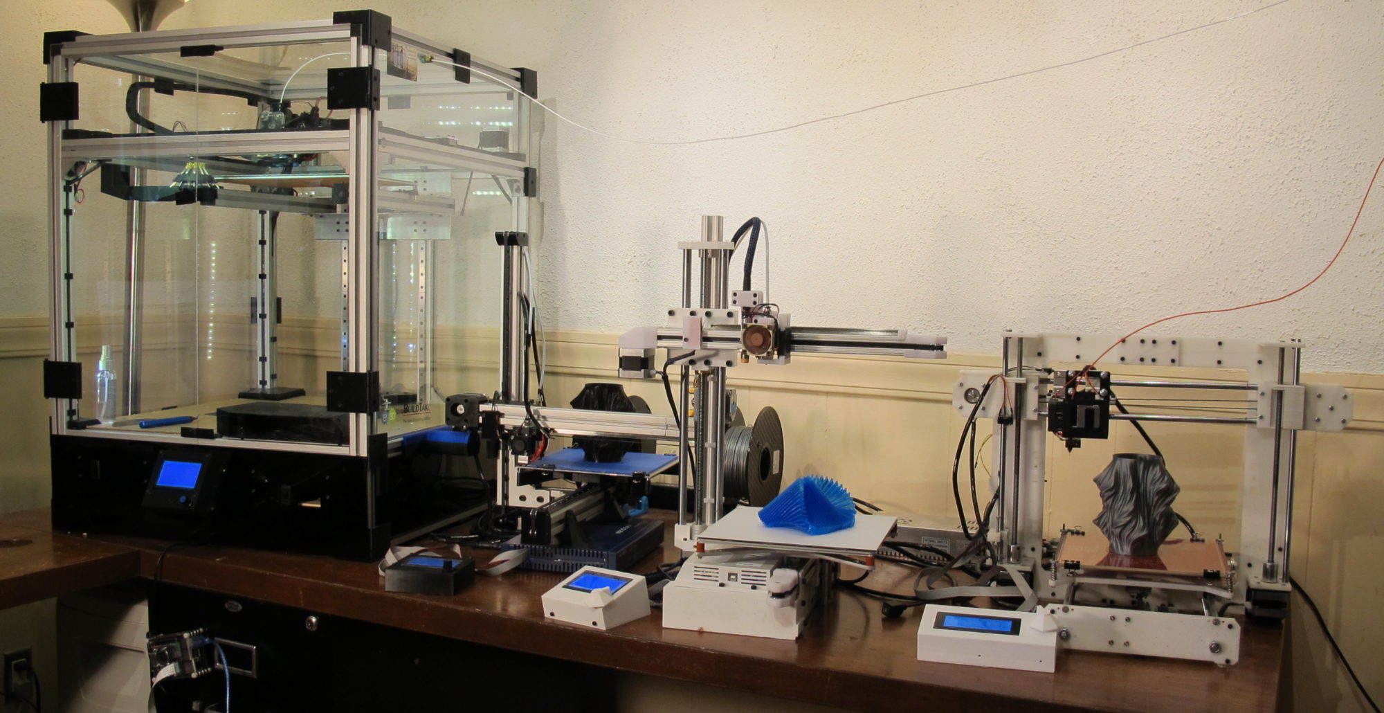
I have used the KFB2.0 board on 2 of my printers. The C3Dt c and the low budget (build on a Netgear Case) Cantilever and am pleased with the way it operates.

The KFB2.0: $18.59 https://amzn.to/2G7xQB8

Here’s a list of all the items I have attached to the KFB2.0

Nema 17 1.7A (5 pack) $48.99 https://amzn.to/2pGlEwO

Mk8 Extruder:

V6 Hotend (12V): $18.99 https://amzn.to/2GfIt0U

For end stop control you can go with two different options:

Stepper Cables: $8.59 https://amzn.to/2I56yHY (JSP HX2.54, which fit the KFB2.0)

12V/30Amp Power supply 19.98: https://amzn.to/2pGXlPD

Heated Bed $31.99 https://amzn.to/2IU6NHp  (optional but I will explain the wiring)

Thermistors $8.99 https://amzn.to/2pG01vW

LCD 12864 $14.99 https://amzn.to/2IU7LU3

Stepper Drivers $10.99 https://amzn.to/2I3eCZS

Fans. I’m a huge fan of the Noctua Fans. They are a bit pricier but worth the SUPER quiet:

(If you want to go with the TMC2130, I recommend getting the real deal from trinamic through Filastruder.com). Cheaper knockoffs are available here. They tend to be not that much cheaper and there some bad reviews out there.

Putting the first pieces together

Like the RAMPS 1.4, the KFB2.0 takes the pluggable stepper drivers that run the stepper motors. The cheap option is to go with the a4988 drivers or the totally awesome TMC2130 (not affiliated, but my upgrade instructions can be found here).

If you go with the a4988 driver you first need to insert the 3 jumpers in each of the diver bays.

In the image above I’ve added the pin descriptions around the middle bay. These pins need to correspond with the pins on your driver circuit board (generally found at the bottom of the board

Insert all stepper drivers and make sure all pins went in on both sides (It’s easy to miss).  Once insert it would look something like this (for the a4988 drivers).

(don’t rely on the orientation of the pot meters in this image. TMC2130 and DRV8825 point the other direction. Look at the pin descriptions on the board and driver and orient accordingly).

Wiring the KFB2.0

Do not attach your board to any backing prior to wiring as all the useful information is found on the back of the board. Beyond that wiring is pretty straight forward. The KFB has the exact same pin outputs as the RAMP 1.4 and as a matter of fact, you select the RAMPS 1.4 board in Marlin when configuring the software.

The above image pretty much show all the different connections you might be making.

Your power source (either 12 Volt or 24 Volt) is attached to the XS 12-24V pins. Polarity is very important here, so make sure Positive and Negative and connected properly (there’s a + and – next to the inputs).

Connecting the Fans

As I mentioned earlier, the KFB2.0 has two continuous outputs for a possible fan. This fan would come on the moment you power up the board. It generally connects to the hot-end fan cooling the heat sink above your hot-end.

Polarity matters and fans should be connected accordingly. They generally come with one black and one red wire. Red = + , Black = –

I personally like the Noctua fans. They’re a bit pricey but it’s worth any every penny due to their quiet operation. The Heat sink fan comes on when you turn on your printer and may still on long after your print is done. With these quiet fans I can’t tell the printer is on by sound.

If you are planning on auto bed leveling, you’ll need the 12Volt output for that. In that case, I would recommend the 5 volt Noctua, leaving the 12Volt for other purposes.

Connecting the Heaters

This board has three outputs for heaters.

  • Hot Bed (Heated Bed)
  • Heater0 (primary extruder)
  • Heater1 (second extruder)

-The Hot bed and Heater0 outputs speak for themselves. Hot bed connects to a heated bed (if you use one); Heater0 connects to the hot-end for your first extruder. They don’t care about polarity but make sure you use wire of proper gauge (14-16) as these carry a lot of Amps.

Heater1 is not as straight forward. If you have double extruders you would expect to connect the second one to this channel. This is not the case (and the only flaw I’ve found on this board to date).  Output for the second extruder is sent to the  Fan  channel (not HEATER1). This is a problem if you choose to have dual extruder with a parts fan (then again you may end up needing more fans). I have not been able to get this to work (most of us won’t need it). I’ve tried tracing its pins back to the board but even after doing so I could not get it powered up.

Connecting the Thermistors

For each of the heated elements you use (beds and extruders) you’ll need to connect the thermistors for temperature feedback. 

Generally your hot-end is shipped with heating cartridge and thermistor but for heated beds this is not always the case. You can buy them loose at Amazon for $8.99 (5-pack).

In most cases you’ll be dealing with a hot-end and heated bed in which case you connect to the TEMP0 (hot-end 1) and TEMP-BED (the bed).

Note: any preliminary testing of your electronics requires at least one thermistor connected to the TEMP0 (without software changes). It’s always handy to have a spare thermistor lying around for such cases.

Connecting the end stops

Most 3D printers only need to have the min end stops attached. Reading the min stop along with specifying the dimensions of your printer will keep your axis within the allowed boundaries. For this setup we’ll connect the min end-stops only.

There’s a variety of end stops available ranging from the simple Micro switches to the wired up Makerbot style switches to optical and inducer type end stops. For this setup we’ll look at the simply micro switches and the Makerbot style end stops.

Given that price range is very similar (you can get micro switched for pennies but they tend to come in packs of 25), the only reason you would choose one of the other is the size. The Makerbot comes pre-wired with a little circuit board but you’ll have to account for more room required.

MakerBot style End Stops

The pre-wired Makerbot style end stops have 3 wires from them. Red, Black and Green.

You may have to crimp your own wires to use a JST-XHP 2.54 3 pin connector on both ends (out of the box they come with the plain pin connectors).

Make sure the Red wire is connected to the vcc pin. Connecting them the other way around will fry your board.

Micro switches

If you choose the micro switch, it’s my experience wiring is a bit easier; you only need two wires.

Solder the wires to the two outside pins of the Micro switch and connect them to the GND and Signal pin on the ramps. These are the two pins towards the outside of the board (GND and Signal)


Since in this configuration the connection is open you will have to flip the configuration in the Marlin software to reverse the signal.

Connecting the LCD

NOTE: Several reviewers for the KFB2.0 complained about LCD connectors soldered on backwards. This requires to cut of the notches from their cables. I ‘m not dismissing this, but I’ve used 3 boards and have not found this to be a problem. I’ve seen similar complaints using different board and wonder if this could be a wiring mixup issue.

The LCD connects to the two EXP1 and EXP2 connectors on the board via the 2 flat cables that most likely came with your LCD unit. You’re LCD board will have the corresponding EXP1 and EXP2 on the back.


Conclusion

I think that covers it. The main downside of the KFB2.0 board is it’s utter lack of specs and documentation. They probably thought they would get away with it because it is so similar to the RAMPS 1.4 (with all the same pin outputs).

What I like about the board is the fact is build much more compact than the RAMPS 1.4 and in fact does act the same.

Some other advantages are an easier means of using the TMC2130 stepper drivers, 12-24volt range ad the 5 and 12volt fan outputs.

I hope this instructional post will mitigate some of the lack of documentation.

If you like what you see here or more importantly if you’ve used some of the designs/instructions I’ve shared via multiple platforms, please consider supporting me via Patreon.com. A few extra dollars a month from enough patrons would certainly help.

Become my Patron at https://www.patreon.com/Core3d_tech

Thank you!!


Compact Cantilever 3D Printer build

My last 3D printer implementation, the Core3D has been mostly done and I love it. All it needs is an automatic nozzle cleaner and I consider it done (sure will find something else to add onto it).

It’s reliable, sturdy and unfortunately big and heavy. What it is not, is something I can pick up and take along to my Parks and Rec presentation later this fall.

For that I’m designing and implementing my 3rd 3D printer build, the Compact 3D. It will be lighter, simpler and I hope most importantly, something I can pick up, drop in the back seat and set up where ever there’s an outlet.

The Compact 3D will be a cantilever printer with little thrills. XYZ (X being cantileved, KFB2.0 controller board,  bowden extruder, adjustable z-enstop, non-heated bed with as little adjustment capabilities as possible.

Each of the axis are built using 3030 aluminum extrusion. each of which ends up being it’s own linear actuator (more on this later).

The entire printer was designed in Fusion 360, prior to implementation.

In this post I will walk you through the different materials used for this build. STL files and designs are available at GrabCad.com and Instructables.com

Generic Axis

Each axis of this printer will be made of aluminum extrusion and will have the t2 belt “wrapper” around the extrusion and linear rail mounted to it. At one end there will be a nema 17 motor, on the other end idlers to guide the belt around/through the extrusion.

The G2 belt will be held in place by the adapter attached to the linear rail’s slider. The ribs on belt will be held in place by the grooves insider the bracket. The belt will be wrapped around the clips.


At this point there is no adjustable tensioner, other than pulling it tight when attaching. Having run for a few weeks now, it seems to work great.

End Stops

Although I’m a big fan of auto leveling, the first implementation of the Compact 3D will have end stops on each of the 3 axis. I will be using the same end stops as used on the Core3D printer. purchased on Amazon.com for $9.99 (set of 5)


Both X and Y will have static cases that can be attached to the extrusion of each axis.

The end stop can be slid into place and tightened by a t-nut on the extrusion.

The Z-axis will be adjustable as the first layer of each print is determined by where the Z-axis ends. It is designed to slide in the groove of the extrusion and can be adjusted by a wheel.

I have uploaded the design for this end stop to GrabCad.com feel free to download.

Bowden Extruder

I’ve never worked with a bowden extruder before and have my doubts about it (play of filament inside bowden tube). However, since this printer will be a cantilever type, I want to limit the load that is put on the X-Axis. Direct extrusion would imply mounting the extrusion motor on the X-rail adding a lot of weight (and momentum) that might be work well for cantilever type printers.

For the bowden drive I’m using an MK8 extruder from ebay  that will be mounted to the Z-Axis.


The hot-end and nozzle are a e3d v6 knockoff from amazon.


The original thought was to go with the standard Ramps 1.4 kit but due to it’s stacked hight I ended up going with a cheap KFB2.0 controller board.


The main topics of this implementation will be the actual build, the installation of the electronics and lastly the configuration of the software.

Materials

I tried to keep the cost down to some extend but did not have to patience to go through China. Most parts were ordered off of Amazon and EBay. I am an affiliate so if you want to help me out, use the links provided.

The backbone of this printer is 3030 Aluminum extrusion. The design requires approximately 1200mm. To be safe (since you will need to cut this) I’d order more. Your best bet is to order this from Ebay.com.

80/20 3030 seriesEbay $17.10 (plus shipping)

Linear Rails 3 x 250 mm Ebay (I was able to get mine at 16.77 per)

Stepper Motors (1.7A) Amazon $51.99 (You can get away with lighter ones)

Idlers 2 5-packs (for the linear actuators) Amazon $8.99

Belt Pulleys (16 teeth) 5-pack Amazon $10.99 (you could also get the 20 teeth)

v6 Hotend (bowden) Amazon $15.98 (You can go for the real E3d but that would blow my budget)

KFB2.0 Controller board Amazon $19.95 (Substitute for RAMP 1.4 Kit, as it doesn’t fit)

DRV8825 Stepper Motor Driver (5 pack) Amazon $11.99

LCD 12864Amazon $14.99

Bed 200×200 (220×220 actual) non-heated: ebay $12.84 (you could go with heated bed but it would require additional power).

NetGear CaseeBay 10.99 + shipping (the design is based on dimension of NetGear FSV318, could be changed though)

MK8 ExtrudereBay $8.33

Cables for Stepper motors Amazon $9.99

Power Brick 12V 8A 96W Amazon $22.50 (comes with adapter that fits netgear power input

Filament (PLA) Amazon $23.00 I did end up using a little ABS for the Hotend bracket. Everything else is PLA.

GT2 Timing belt Amazon $8.99

USB ConnectorAmazon $6.79 (optional but makes for nicer finish)

Circuit BoardAmazon $6.99 (optoinal to add jsx connectors. Cables could go directly to KFB2.0 Board)

Square Nuts M3 Amazon $6.99 (only need 7)

Hex nuts M3 Amazon $7.05

T-nut 30 series (m6) 100 pack Amazon $13.99 (Again only need 3)

T-nut 30 series (m3) 50 pack AlieXpress $8.78 (you can get them from amazon in 10 packs for way more but faster)

Pan head screws M3 30mm Amazon $8.72 (only need 20)

Hex socket screws of various sizes Amazon $13.99

JST 2.54 connectors (2/3/4/5/6) Amazon $9.99 (the KFB2.0 is all JST connectors. You may have to crimp your wires accordingly.

Cable wire Wrap (4m) Amazon $6.18

3030 Corner Bracket (come in 10 pack) Amazon $10.99 (only need 2)

As you can see things start adding up (little over $400). One has to be realistic that all the little items matter and cost money. I’ve tried to represent as close as possible all the items needed for this build.

All of this was ordered through Amazon Prime. If you haven’t tried it, check out the free trial here:

If you have time and patience many of these items can be found on AliExpress.com for much much less. Delivery times can run up to several weeks, so again, patience is the name of that game.

Step 2: Linear Actuators

All three axis are based on the same design and are in fact standalone linear actuators that could be used for any purpose.

Components needed for each of the actuators:

Linear Rail (for this design 250mm but could be longer)

3030 Aluminum extrusion (375mm for Z-axis, 320mm for X-Axis and 320 for Y Axis). If you go with longer linear rail then go with more extrusion.

Stepper motor with belt pulley for each actuator. In this design I used 1.7A stepper but I think you can easily go with 1A steppers.

End-stop for each actuator. The end stops are Gowoops 5 PCS of Mechanical Endstop Switch with Cable. The cases in which they are attached are to be 3D printed.

GT2 timing belt

3 idlers to guide the GT2 belt

End casings for the actuator to be 3D printed

6 pan head 30mm m3 screw

Based on the Axis different linear guide slider Connectors/belt tensioners.

3D printer files for each of the axis are:

X-Axis:

  • IdlerCapFront (Mirror).stl,
  • IdlerCapBack (Mirror).stl
  • NemaCapFront (Mirror).stl
  • NemaCapBack (Mirror).stl
  • EndStopCaseX.stl
  • HotEndAdapter.stl
  • HotEndBracket.stl
  • LinearAdapterTensionClip.stl (2x)

Y-Axis:

  • IdlerCapFront.stl,
  • IdlerCapBack.stl
  • NemaCapFront (Mirror).stl
  • NemaCapBack (Mirror).stl
  • EndStopCaseY.stl
  • LinearAdapterY.stl
  • LinearAdapterTensionClip.stl (2x)

Z-Axis:

  • IdlerCapFront (Mirror).stl,
  • IdlerCapBack (Mirror).stl
  • NemaCapFront (Mirror).stl
  • NemaCapBack (Mirror).stl
  • LinearAdapterZ.stl
  • LinearAdapterTensionClip.stl (2x)
  • AdjustableEndStopCaseZ.stl
  • AdjustableEndStopWheel.stl
  • AdjustableEndStopWheelHouseBottom.stl
  • AdjustableEndStopWheelHouseTop.stl

The Nema Endcaps are connected via a 30mm pan head screw (with idler in between) and 4 pan head screw connecting the Nema Stepper motor. In the back caps there is space to place hex nuts.

Once you’ve connected all the idlers (two in the End caps and one in the Nema caps) and attached the Nema Stepper moter to the Nema caps, you can weave the GT2 belt through (and around the pulley) and pull both ends up to the Linear rail slider.

Keep several inches past the linear slider on each end as you will be wrapping them around the tension clips and inserting these into the adapter.

I have found it easiest to do this with a lot of slack, then connect the adapter to the slider with four hex Socket screws (6mm) and only tighten one side of the belt. With pliers you can now tighten the belt on the other side (until the belt is real tight) and screw the remaining screws.

The end-stop casings are a real close fit to the actual end stops. Make sure you connect the wiring prior to sliding he end stop in the case. The case can then be attached to the extrusion with a T-nut and 20mm hex socket screw

Step 3: The Case

I used a netgear fsv318 Router as the base for the printer. It can hold the electronics and comes equipped with an on/off button as well as a power connection.

In order to prepare the case, I opened the case and cut the circuit board next to the power adapter leaving the board with the on/off swich and power adapter.

I did some rewiring to get plus and minus wires that can originate from the power adapter and can be switches on/off with the existing switch. This does require the ability to use a volt meter and to solder to figure out where and how to connect the new wiring.

I created a controller board base that uses the existing screw holes in the Netgear case and allows for the addition of a circuit board that can connect all the wiring (via jst connetors).

The Y-axis is connected via two 3D printed brackets that can be screwed into the case (by means of hex socket screws and nuts) and in turn wraps around the extrusion, to be connected via 4 t-nuts and 15mm hox socket screws.

The 3D printed items for this step are:

  • bodyClamp.stl
  • bodyClamp_2.stl
  • MotherBoardBracket.stl

Step 4: Electronics

For this implementation I ended up using a KINGPRINT KFB2.0 Controller Board (for Reprap Mendel Prusa I3 Kossel 3D Printer). I had initially order the usual RAMPS 1.4 kit but figured out quickly enough that stacked up it would exceed the height of the Router case (intended to hold the electronics).

At the time of ordering the KFB2.0 there was no documentation, whatsoever, to be found on it but it seemed to be simply everything that was on a RAMPS 1.4 shield (and then some) and for less than $20 I felt it was worth a try.

Turns out I’m pretty pleased with it. It does exactly the same as a RAMPS 1.4 shield and it takes the same software. It is basically an Arduino Mega 2560 with all the connectors needed for stepper drivers and all other 3D printer related connections.

This board can actually take 24 Volt (as opposed to only 12V for the RAMPS 1.4).

The only difference is all the connections. These are all JST 2.54 connectors and thus I did end up crimping a lot of wires. The stepper motor wires I put in the material list already use JST 2.54 so that should make it is bit easier.

In the case of my implementation I decided to leave all connections outside of the box and prepared a circuit boars with JST connetors for X, Y, Z steppers and end stops, Extruder, hotend and thermistor. I left room for possibly a second extruder.

I had hope that wiring the way I did, I could easily open the case and get to the electronics. As you can see in the images, I can do that to some extend but opening and closing the case is a pretty tight fit.

In order to pass through the wires for the LCD, I had to saw open one of the side gaps. The LCD wiring fits nicely.

I also added a secondary connector for my power brick that I can reach when the case is half open. Optional but handy.

When adding the stepper drivers, don’t forget to insert the proper jumpers (all three for each driver) to get the most accurate steps for this configuration 1/16 steps.

Make sure the drivers have their potential-meter screw pointing towards the Main Board Chip (see images). Inserting them the wrong way I believe will fry components beyond repair.

The same goes for the End stop connections. The signal is towards the outside of the board.

Most connections are printed on the bottom of this particular controller board, so check it out first prior to screwing the board down.

I’ve included an STL for a case that can be used to house the LCD. I’ve left it open in the back as I haven’t figured out if I want to connect it somehow to the case or if I want to leave it loose (I pick it up when operating it).

LCD Case: LCDCase.stl

Step 5: Bed and Assembly

At this point all components to the printer are in place. All that is left to complete the build is assembly.

The printer bed is supported by a 3D printer frame on which an aluminum bed can be added (via screws and springs).

The MK8 Extruder can be attached to the Z-axis with the provider Extruder Bracket: ExtruderBracket.stl

The STL for the 3D printed bed is: BedFrame.stl

All that is left is to attach all three axis to each other and to the case subsequently.

The X-Axis is attached to to Z-Axis via the Linear adapter on the Z-Axis by means of three 6M t-nuts and 3 M6 Hex socket screws (10mm)

The Z-Axis is attached to the Y-Axis via a “bridge” using 3030 Extrusion and 2 corner brackets.

It may take some effort and a water level to make sure the connections make perfect 90 degree angles. Not putting in that effort may make for some wonky prints.

Step 6: Software Setup

The KingPrint KFB2.0 board runs marlin software which can be downloaded at:

https://github.com/MarlinFirmware/Marlin

Once loaded locally it will need some configuration to get it to work with this printer build.

Most changes will be made to the configuration.h file (attached)

changes:

Endstops require inverting

#define X_MIN_ENDSTOP_INVERTING true // set to true to invert the logic of the endstop.
#define Y_MIN_ENDSTOP_INVERTING true // set to true to invert the logic of the endstop. 
#define Z_MIN_ENDSTOP_INVERTING true // set to true to invert the logic of the endstop.

Steps based on 1/16 and 16 teeth and MK8 extruder

#define DEFAULT_AXIS_STEPS_PER_UNIT { 100, 100, 100, 92.6 }

Since the bed is only supported by the linear slider, there will be more vibrations. The Jerk needs to be pushed down (maybe even further than the numbers shown)

#define DEFAULT_XJERK                 10.0
#define DEFAULT_YJERK                 10.0
#define DEFAULT_ZJERK                  0.4
#define DEFAULT_EJERK                  5.0

based on current build (this may differ based on stepper wiring)

#define INVERT_X_DIR false
#define INVERT_Y_DIR false
#define INVERT_Z_DIR false

based on the current build and it’s dimension I had to set the X Y and Z boundaries

// Travel limits after homing (units are in mm)
#define X_MIN_POS -17
#define Y_MIN_POS -37
#define Z_MIN_POS 0
#define X_MAX_POS 200
#define Y_MAX_POS 200
#define Z_MAX_POS 270

Since my end stop are outside the bounds of the bed I need to change the manual home settings

// Manually set the home position. Leave these undefined for automatic settings.
// For DELTA this is the top-center of the Cartesian print volume.
#define MANUAL_X_HOME_POS -17
#define MANUAL_Y_HOME_POS -37
#define MANUAL_Z_HOME_POS 0

Turn on Full graphics LCD and SD card support

//#define ULTRA_LCD   // Character based
#define DOGLCD      // Full graphics display
/**
 * SD CARD
 *
 * SD Card support is disabled by default. If your controller has an SD slot,
 * you must uncomment the following option or it won't work.
 *
 */
#define SDSUPPORT

Enable the proper LCD

//
// RepRapDiscount FULL GRAPHIC Smart Controller
//  http://reprap.org/wiki/RepRapDiscount_Full_Graphi...
//
#define REPRAP_DISCOUNT_FULL_GRAPHIC_SMART_CONTROLLER

Because the Z-axis is belt driven (whereas most are lead screw driven) I end up with an issue when a print is stopped. If I click STOP PRINT (or even if a print is done) the Z-Axis will loose power and drop like a rock. This can damage your print or in worse case shatter your bed. For this I made some changes to the more hidden code.

Whenever a SD_FINISHED_RELEASECOMMAND is issued power is dropped to all stepper which for this printer can be bad (dropping Z-axis). I expanded the code in Configuration_adv.h to add to more command in that event.

#define SD_FINISHED_STEPPERRELEASE true  //if sd support and the file is finished: disable steppers?
  //compact
  #define SD_FINISHED_XYHOMECOMMAND  "G28 X0 Y0"  
  #define SD_FINISHED_ZHOMECOMMAND  "G0 Z0"  
  #define SD_FINISHED_RELEASECOMMAND "M84 X Y E" // You might want to keep the z enabled so your bed stays in place.
  
  //#define SD_FINISHED_RELEASECOMMAND "M84 X Y Z E" // You might want to keep the z enabled so your bed stays in place.

I also changed the release command to NOT drop power on the Z-Axis stepper. Now when the stop command is executed, the printer will first home to X0Y0 (which should get out of the way of any print. Subsequently the printer homes to Z0 and then drops power to X and Y (not Z).

In the stepper.ccp file the code has been changed to execute these new commands.

#ifdef SD_FINISHED_RELEASECOMMAND
      if (!cleaning_buffer_counter && (SD_FINISHED_STEPPERRELEASE)) {
        enqueue_and_echo_commands_P(PSTR(SD_FINISHED_XYHOMECOMMAND));
        enqueue_and_echo_commands_P(PSTR(SD_FINISHED_ZHOMECOMMAND));
        enqueue_and_echo_commands_P(PSTR(SD_FINISHED_RELEASECOMMAND));
        
      }
    #endif
    _NEXT_ISR(200); // Run at max speed - 10 KHz
    _ENABLE_ISRs(); // re-enable ISRs
    return;
  }

These are all the changes that were made to make this printer run.

Step 7: Conclusion

So this was all it took to build the Cantilever printer I set out to build. The materials list I believe is complete but mostly sourced from Amazon. The build can be lot cheaper if you dig a little deeper into AliExpress.

The printer performs fine for the budget it was built on. Having the entire bed rest on a single linear slider is a bit of a stretch but seems to work.

Step 8: STL Files and Design

All 3D printed parts that have been referenced in this build can be found in the uploaded STL_Files.zip.

The entire design can be downloaded from GrabCad at https://grabcad.com/library/cantilever-3d-printer-1

All items where printed on another custom built printer of mine. That one is a bit more complicated than this build but maybe one day I’ll create an instructable for it as well

Continue a failed print

If you searched for “how to continue a failed print”, you probably recognize this image.

It’s the bottom part of a print  left exposed after the Titan extruder ground the filament and it no longer fed  (shame on you e3D, this never happened with my MK8).

In prior occurrences I’ve tried to tighten the knob where it is now to the point, it can’t go no more.

The head is not clogged, if I take out the ground filament, re-feed it and  tell it to extrude, it does. So today instead of starting over, I tried something different, I attempted to continue the failed print.

Here is how I did it.

I first took a very close look at the print on the board:

Step 1: Find a reference point from which you can count the layers printed. For example in the image below I can easily count the layers based on the circled reference point.

in the print I can see 4 layers printed above the end of the curve.

Step 2: Open Slic3r or whatever tool you used to slice the object and make sure you have the same settings (layer hight most importantly). If the object was scaled before make sure it is scaled the same.

Also take note of any offset used against the z axis. In my case that happened to be -0.2 which means my print started the first layer at Z0.0

Step 3: Open the preview and go to the layer you’ve identified as the last layer in the print.

Slic3r now tells me that the print ended extruding at 24.80 mm

Step 4: open the original gcode file used in the failed print (make a copy if you want to keep the original.

At this point thing can get a little tricky. Each printer uses its own g-code meta information, that may or may not be required for your print to continue.

This for example is my initial g-code:

M190 S110 ; set bed temperature and wait for it to be reached
G1 Z15 F5000 ; lift Z to avoid clamps
G28 XY
M109 T0 S215; pre heat so it can drop filament prior to moving to corner bed.
G28; home 
G29; auto level

G1 Z5 F2000 ; lift nozzle

G21 ; set units to millimeters
G90 ; use absolute coordinates
M82 ; use absolute distances for extrusion

For some of you, some of  this code needs to remain. Some MUST GO.

Doing an automatic home (G28) will probably hit your failed print in place. In my case my Z-home is done at the center of the plate. CAN’T DO THAT.

The unit/coordinate g-code may have to remain (Seemed not necessary for my printer).

In the g-code file search for the z coordinate where your print dropped its last successful line.

in this same that would be 25 (24.80 plus 0.2 for layer height).

Step 5: remove all executed g-code. In my case I removed ALL g-code prior to this line.

adapted gcode

Step 6: depending on what is left as your header g-code. you may have to set temperatures and perform homing.

Instead of leaving this “header” g-code in place I used Pronterface to do the -heating, the X and Y homing and I had to do a manual z-homing by putting the bed up to the nozzle and setting z0 (G92 Z0).

Step 7: Once temperature is set and homing is done, make sure your nozzle is position HIGHER than the last layer on your print. Depending on your printer, it may hit the print in place while positioning to its starting point otherwise.

At this point you can start your print based on the newly save g-code file.

Conclusion

Is this solution perfect? NO, it’s a hack, but in cases of prototyping where your more interested in shape than print quality, this will do in many cases.

For those of you having payed close attention, I made a mistake in mine. I restarted the print at Z 25 When I should have set it to start at 24.8 as my z-offset was -0.2 and thus layer 1 started at Z 0.

I solved this by adjusting the screws around the bed. It did the trick. below are images of the print after restart and the end result. You can clearly see the line where the print was picked up but again, In this case I wanted a finished piece and quality wasn’t the highest priority.

Continued print after updating gcode file

So there you have it. Instead of restarting a 7 hour print that was 5 hours in I managed to alter the code and restart the print (which took me about 30 minutes).

Saved myself some time and material

Upgrading the Core3D extruder assembly

When I built my first 3D printer which was based on the Prusa I3, I went with MK7 extruder clone from Aliexpress and it worked great. Great to my standards (at the time) that is. It is no longer available so when I designed the Core3D printer, I went with the MK8 extruder found on the same site. The dimensions are pretty much the same as those for the MK7.

MK8 design and issues with it.

I designed the extruder to be “suspended” underneath the extruder assembly. I went for mounting it under because the MK8 has the stepper motor mounted behind the actual extruder.  The design in Fusion 360 below shows the MK7 extruder as I never updated it to MK8. The specs remain the same though.

original MK7 extruder design for Core3D

Here is the actual implementation of the full extruder assembly.

A few things have bothered me with this design and implementation.

-Top to bottom the entire setup is 120 mm (4.72″) which is too much, the space below the X-axis used would make for close to 70 mm more build space (along the Z-axis).

-The use of aluminum and the shear size of the assembly, make it weigh close to 825 grams. Too much weight (in my opinion) to be accelerating/jerking around.

-The MK8 is a knock-off. A $1,200 printer (parts only) deserves better. I keep hearing how much better the E3d extruders are, compared to the knock-offs.

-Lots of issues loading new filament. The space between the top and the heater nozzle have too much room allowing for the filament to miss the hole.

Redesign with E3D titan extruder and hotend

Following are a few of things I wanted to achieve with the redesign:

  • Lower the height of the extruder assembly.
  • Lower the weight of the the assembly.
  • Possibly lower the width allowing for more motion along the X-axis
  • Achieve higher quality of prints.

Lowering the height

The E3D titan extruder (direct) has much more room between the stepper motor and actual hot end (Compared tot the MK8). The image below shows both extruder designs. Notice how the new Titan Extruder is much higher in height but what matters is the distance between Stepper and hot-end.

For the MK8, the distance between the bottom of the extruder and bottom of nozzle is about 25 mm.

For the Titan Extuder, this is closer to 46 mm. The difference means that I can mount the stepper motor/extruder above the X-axis rail and let the hot-end bridge the distance to below the rail.

The following image shows the true gains in Z-axis space when I place the two extuders in relationship to the X-axis rail they are riding on.

By “wrapping” the extruder around the rail, I gain about 45 mm more Z-axis to print at.

Interestingly, my bed wasn’t designed to go that high originally. It turns out the cable drag chain wasn’t put in place with that much height in mind. I had to remove some shackles to accommodate the extra gained space.

lack of room for wire drag chain

Lowering weight of Extruder Assembly

Here is the break down of what my old extruder assembly weighs:

Top Plate: 41 gr
Bottom plate: 41 gr
extruder bracket: 80 gr
plastic: 80 gr
belt clips:  11 gr
bolts/nut:  18 gr
Stepper: 280 gr
extruder:  96 gr
Hot end: 74 gr
Slider:  32 gr
cooling fan: 13 gr
fan duct:  11 gr
Inductive Sensor: 46 gr

Total:  823 gram

The numbers for the new extruder are as follows:

Top Plate: Gone
Bottom plate: Gone
extruder bracket: Gone
plastic: 27 gr
belt clips:  8 gr
bolts/nut:  8 gr
Stepper: 127 gr
extruder:  60 gr
Hot end: 44 gr
Slider:  32 gr
cooling fan: 16 gr
fan duct:  11 gr
Inductive Sensor: 46 gr

Total:  386 gram

By far the heaviest component is the stepper motor and since the Titan extruder has a 3:1 gear reduction, I can get away with a pancake stepper motor. This reduces the weight be an additional 140 grams.

New weight would come down to 386 grams

Bigger impact on rest of CoreXY

The nature of the Titan’s extruder allows me to “wrap” the entire extruder assembly around the X-axis rail. This “Wrapping will gain me close to 50 mm of additional Z-axis range.

All belts in the former Core3D design run over the X-axis as follows:

belt running atop the X-axis

in the new design the stepper motor mounted behind the extruder glides fairly closely to the rail so no more room for the belts.

The new extruder assembly required a new belt configuration. In the new implementation all belts will run underneath X-axis and inside the extrusion frame.

new belt placement below the x-axis rail

The most notable difference are:

Both X/Y stepper motors now have been turned upside down (had to figure out the firmware on that one).

The X-axis end-stop has been moved on top of the rail (in a adjustable slider)

New X Endstop on top of rail

The idlers opposite of the steppers have been placed on a single axis below/inside of extrusion frame.

Idlers before
Idlers after

A minor concern with this design is the idlers being held in place by an ABS printed corner bracket. The actual layers holding the idlers aren’t very thick. Since the belts are kept pretty tight, I wonder if this will break (it hasn’t yet).

When all is said and done

The new design has been up and running for a week now and I’m happy with the results. The new extruder operates as expected. The first 3D Benchy came out great.

This is what the new setup looks like:

New Core XY with E3d Titan Extuder

Here it is at work:


Why the Core3D printer uses CoreXY

After reading this, please consider supporting me at GoFundMe

The Core3D printer was implemented using CoreXY as its method of motion. When I first learned about it, it reminded me of my etch a sketch. I realize, not the best founded reason for approaching something new.

The other most common methods are Delta and Cartesian. Not sure Cartesian is the right name for one of them as all methods apply to X, Y and Z coordinates. I don’t don’t  René Descartes had in mind how motors would operate to reach X=0, Y=0 and Z=0.

Let look a bit closer at all three methods.

Cartesian

The most common method in the world of 3D Printing is referred to as Cartesian motion. An example of this would be the Original RapRap implementation. Each axis has it’s own dedicated stepper motor(s). One for the X-Axis which travels up and down along the Z-axis. One Stepper motor for the Y-Axis which in case of the Prusa pulls the bed back and forth and 1 or 2 stepper motors for the Z-Axis which in this case lifts the entire X-Axis.

source adapted image

This method is the default implementation for the Marlin Firmware which operates a large portion of the 3D printer world.

Delta

The Delta 3D printer uses a completely different mechanism. The extruder head is controlled by 3 arms that move up and down their own (parallel) rails. The software calculates the proper movement to come to X, Y and Z coordinates.

source image

In the printer above three stepper motors all move in parallel but independently (up and down). The Delta printer is probably the second most available printer. From what I’ve read, trouble shooting is not as straight forward as the motion is is much less intuitive than the standard “Cartesian” motion.

Core XY

Less common, although seemingly on the rise is the Core XY motion. The best way to explain Core XY is to refer to coreXY.com but lets use the Core3d printer as a reference here.

Core3D Printer CoreXY design

X and Y are controlled by two stationary  stepper motors. Neither motor is dedicated to a single axis, instead the firmware will use the motors in tandem to reach the different X and Y coordinates.

Don’t worry about the math: Marlin Firmware takes care of all of this but in case you’re interested:

ΔX = 0.5(ΔA + ΔB), ΔY = 0.5(ΔA – ΔB), ΔA = ΔX + ΔY, ΔB = ΔX-ΔY

In the case of the Core3D printer, the Z-axis is controller by a single stepper moving the bed up and down.

Core3D printer X/Y/Z assembly using CoreXY

The nice thing about all these mechanisms of motion is that you don’t have to figure it out. CoreXY is much less intuitive than the normal “Cartesian” but as far as I’m concerned it is just a configuration in the Marlin software. I’ll write a more detailed post on the configuration.

So why Core XY for the Core3D printer?

I’ll be real honest here, I could have gone with ordinary Cartesian like the Prusa but why settle for ordinary? My primary goal was to create an enclosed printer with lots of bells and whistles.

The anecdotal word on CoreXY is that:

  • it is more accurate. The fact that both stepper motors are stationary adds to that accuracy . In most 3D printers, one stepper motor moves the entire bed (which, with high builds and high speed, can introduce wobble). In the Cartesian implementation, the motor controlling the X-axis moves up and down with the Z-Axis (be it very small increments each layer) and the Z-axis lifts the entire X-axis installation. It is important to note that this accuracy depends a lot on the weight of the extruder assembly and sturdiness of the frame it sits in.
  • It can operate faster.  Yes, I can run the head back and forth at 10,000 mm/sec but that doesn’t make it accurate. As a matter of fact, I don’t think extruders can even handle that type of speed.
  • The bed doesn’t move along the Y-axis (stationairy on delta as well) so that makes for more stability. In General the bed moving around isn’t that much of an issue as long as it is light enough. When you move to metal bed, not to mention bigger prints, weight can start becoming an issue moving back and forth that fast.

I have a feeling, proponents of the other types of motion will argue or put forth similar points to defend their methods. I’m tempted to create a second version of my printer and have it implement the Cartesian motion for X and Y (I would leave the Z-Axis as is).

I thought about doing something with delta but I was put off by some of the comments around difficulty with troubleshooting. It also feels to me like the 3 spindly arms can’t withstand much force.

I went with CoreXY as, personally, I think it’s more elegant. It’s not forced to move clunky (in some cases) heavy stepper motors and extruders around. That said, the Core3D printer can actually use some improvement there, as the current construction of the extruder/brackets/inducer still ended up quite heavy.

Core3D Extruder assembly on CoreXY
Current Core3D extruder assembly

One of my next updates will be that of reducing the size and weight of the extruder assembly.