Continue a failed print

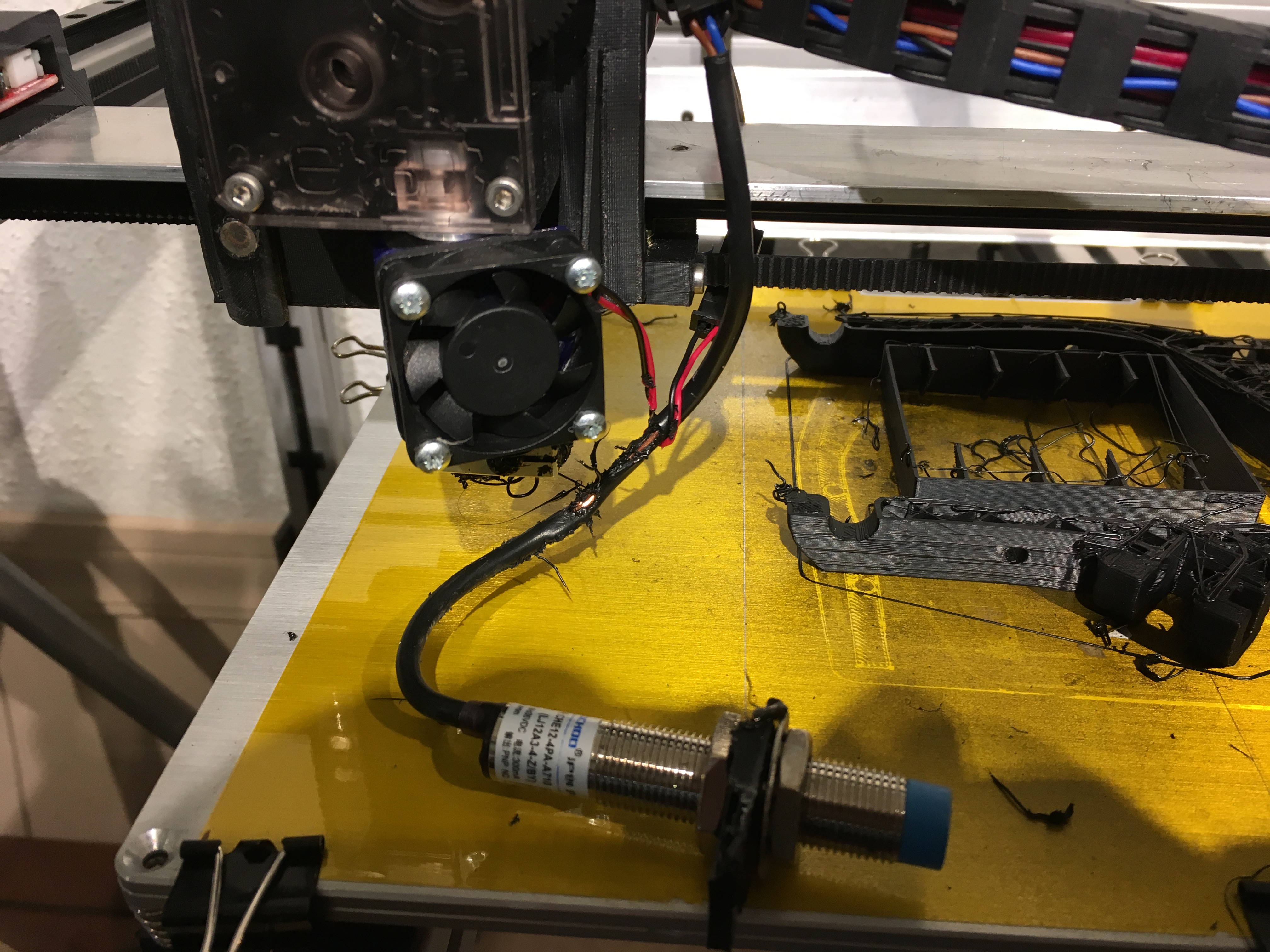
If you searched for “how to continue a failed print”, you probably recognize this image.

It’s the bottom part of a print  left exposed after the Titan extruder ground the filament and it no longer fed  (shame on you e3D, this never happened with my MK8).

In prior occurrences I’ve tried to tighten the knob where it is now to the point, it can’t go no more.

The head is not clogged, if I take out the ground filament, re-feed it and  tell it to extrude, it does. So today instead of starting over, I tried something different, I attempted to continue the failed print.

Here is how I did it.

I first took a very close look at the print on the board:

Step 1: Find a reference point from which you can count the layers printed. For example in the image below I can easily count the layers based on the circled reference point.

in the print I can see 4 layers printed above the end of the curve.

Step 2: Open Slic3r or whatever tool you used to slice the object and make sure you have the same settings (layer hight most importantly). If the object was scaled before make sure it is scaled the same.

Also take note of any offset used against the z axis. In my case that happened to be -0.2 which means my print started the first layer at Z0.0

Step 3: Open the preview and go to the layer you’ve identified as the last layer in the print.

Slic3r now tells me that the print ended extruding at 24.80 mm

Step 4: open the original gcode file used in the failed print (make a copy if you want to keep the original.

At this point thing can get a little tricky. Each printer uses its own g-code meta information, that may or may not be required for your print to continue.

This for example is my initial g-code:

M190 S110 ; set bed temperature and wait for it to be reached
G1 Z15 F5000 ; lift Z to avoid clamps
G28 XY
M109 T0 S215; pre heat so it can drop filament prior to moving to corner bed.
G28; home 
G29; auto level

G1 Z5 F2000 ; lift nozzle

G21 ; set units to millimeters
G90 ; use absolute coordinates
M82 ; use absolute distances for extrusion

For some of you, some of  this code needs to remain. Some MUST GO.

Doing an automatic home (G28) will probably hit your failed print in place. In my case my Z-home is done at the center of the plate. CAN’T DO THAT.

The unit/coordinate g-code may have to remain (Seemed not necessary for my printer).

In the g-code file search for the z coordinate where your print dropped its last successful line.

in this same that would be 25 (24.80 plus 0.2 for layer height).

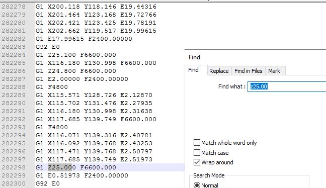
Step 5: remove all executed g-code. In my case I removed ALL g-code prior to this line.

adapted gcode

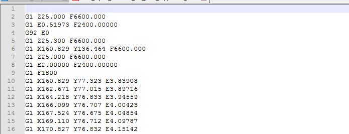
Step 6: depending on what is left as your header g-code. you may have to set temperatures and perform homing.

Instead of leaving this “header” g-code in place I used Pronterface to do the -heating, the X and Y homing and I had to do a manual z-homing by putting the bed up to the nozzle and setting z0 (G92 Z0).

Step 7: Once temperature is set and homing is done, make sure your nozzle is position HIGHER than the last layer on your print. Depending on your printer, it may hit the print in place while positioning to its starting point otherwise.

At this point you can start your print based on the newly save g-code file.

Conclusion

Is this solution perfect? NO, it’s a hack, but in cases of prototyping where your more interested in shape than print quality, this will do in many cases.

For those of you having payed close attention, I made a mistake in mine. I restarted the print at Z 25 When I should have set it to start at 24.8 as my z-offset was -0.2 and thus layer 1 started at Z 0.

I solved this by adjusting the screws around the bed. It did the trick. below are images of the print after restart and the end result. You can clearly see the line where the print was picked up but again, In this case I wanted a finished piece and quality wasn’t the highest priority.

Continued print after updating gcode file

So there you have it. Instead of restarting a 7 hour print that was 5 hours in I managed to alter the code and restart the print (which took me about 30 minutes).

Saved myself some time and material

Proximity-Sensor-Detection LJ12A3-4-Z-BX vs LJ12A3-4-Z/BY wiring

I had a little mishap with my extruder head. In my absence the Proximity sensor had broken off and got tangled near the hot-end. Suffice it to say, that was the end of it.

The destroyed sensor was a DIYmall LJ12A3-4-Z/BY Proximity Switch DC 10-30V PNP I bought on Amazon(Yes I’m an affiliate).

The sensor takes in 12 volts and comes with a voltage regulator that reduces the signal to 5 volt(ish). I personally like the voltage regulator as I don’t have buy bulk resistors just to get 2 resistors soldered on.

Here is how the LJ12A3-4-Z/BY  was wired and how it worked for me for some time. And yes I do love the auto leveling feature.

wiring compliments of DIYmall (where I purchased the sensor). My sensor had a blue head though

Alternatively you can use the resistors:


Now that it was broke, I had to replace it with my spare sensor but it did not work as expected. I wired up the sensor in the same manor and got the little light to work as expected when approaching the sensor with a metal object.

Marlin however kept reading the z-min as triggered, regardless of what the little light on the sensor indicated. I even went into the firmware and futzed around with the  Z_MIN_ENDSTOP_INVERTING but to no avail. No surprise as the z_min was triggered regardless of signal.

Turns out the spare sensor I had was NOT the LJ12A3-4-Z/BY but instead it was the LJ12A3-4-Z/BX (that’s right, I’m affiliated here as well). This where things got a little complicated.

Every site you visit on wiring references either the voltage regulator or resistors (actually resistors seems to be the more prevalent way of implementation).


Even in the case of  the LJ12A3-4-Z/BX I’ve seen the schematics using the resistors. For some reason the LJ12A3-4-Z/BX  does not seem to work with the voltage regulator and it might work with the resistors but I really DON’T NEED either.

The specs for the  LJ12A3-4-Z/BY are as follows: DC 10-30 Volt

The specs for the  LJ12A3-4-Z/BX as follows: DC 6-36Volt

Instead of connecting the sensor to the 12 Volt input (like required for the BY) the LJ12A3-4-Z/BX can be connected to the 5 Volt output on the actually stop. The 5 Volt is enough to get the proper signal (even though the specs state 6-36V).

directly powered from 5 volt on z-stop


UPDATE: Today I tried connecting my second  LJ12A3-4-Z/BX to a KFB2.0 board and IT DID NOT WORK using the 5 volts. I ended up using the resistor method (above) using 2K and 1K resistors.

The reason it may not have worked this time could be explained by one of two ways:

  1. Not all   LJ12A3-4-Z/BX are created equal, anecdotal information out there seems to indicate this
  2. The KFB board outputs 4.9 volts as opposed to the 5.1v on my previous RAMPS 1.4 board. I’m wondering of this little difference may just put it too far from the 6 Volts required.


Upgrading the Core3D extruder assembly

When I built my first 3D printer which was based on the Prusa I3, I went with MK7 extruder clone from Aliexpress and it worked great. Great to my standards (at the time) that is. It is no longer available so when I designed the Core3D printer, I went with the MK8 extruder found on the same site. The dimensions are pretty much the same as those for the MK7.

MK8 design and issues with it.

I designed the extruder to be “suspended” underneath the extruder assembly. I went for mounting it under because the MK8 has the stepper motor mounted behind the actual extruder.  The design in Fusion 360 below shows the MK7 extruder as I never updated it to MK8. The specs remain the same though.

original MK7 extruder design for Core3D

Here is the actual implementation of the full extruder assembly.

A few things have bothered me with this design and implementation.

-Top to bottom the entire setup is 120 mm (4.72″) which is too much, the space below the X-axis used would make for close to 70 mm more build space (along the Z-axis).

-The use of aluminum and the shear size of the assembly, make it weigh close to 825 grams. Too much weight (in my opinion) to be accelerating/jerking around.

-The MK8 is a knock-off. A $1,200 printer (parts only) deserves better. I keep hearing how much better the E3d extruders are, compared to the knock-offs.

-Lots of issues loading new filament. The space between the top and the heater nozzle have too much room allowing for the filament to miss the hole.

Redesign with E3D titan extruder and hotend

Following are a few of things I wanted to achieve with the redesign:

  • Lower the height of the extruder assembly.
  • Lower the weight of the the assembly.
  • Possibly lower the width allowing for more motion along the X-axis
  • Achieve higher quality of prints.

Lowering the height

The E3D titan extruder (direct) has much more room between the stepper motor and actual hot end (Compared tot the MK8). The image below shows both extruder designs. Notice how the new Titan Extruder is much higher in height but what matters is the distance between Stepper and hot-end.

For the MK8, the distance between the bottom of the extruder and bottom of nozzle is about 25 mm.

For the Titan Extuder, this is closer to 46 mm. The difference means that I can mount the stepper motor/extruder above the X-axis rail and let the hot-end bridge the distance to below the rail.

The following image shows the true gains in Z-axis space when I place the two extuders in relationship to the X-axis rail they are riding on.

By “wrapping” the extruder around the rail, I gain about 45 mm more Z-axis to print at.

Interestingly, my bed wasn’t designed to go that high originally. It turns out the cable drag chain wasn’t put in place with that much height in mind. I had to remove some shackles to accommodate the extra gained space.

lack of room for wire drag chain

Lowering weight of Extruder Assembly

Here is the break down of what my old extruder assembly weighs:

Top Plate: 41 gr
Bottom plate: 41 gr
extruder bracket: 80 gr
plastic: 80 gr
belt clips:  11 gr
bolts/nut:  18 gr
Stepper: 280 gr
extruder:  96 gr
Hot end: 74 gr
Slider:  32 gr
cooling fan: 13 gr
fan duct:  11 gr
Inductive Sensor: 46 gr

Total:  823 gram

The numbers for the new extruder are as follows:

Top Plate: Gone
Bottom plate: Gone
extruder bracket: Gone
plastic: 27 gr
belt clips:  8 gr
bolts/nut:  8 gr
Stepper: 127 gr
extruder:  60 gr
Hot end: 44 gr
Slider:  32 gr
cooling fan: 16 gr
fan duct:  11 gr
Inductive Sensor: 46 gr

Total:  386 gram

By far the heaviest component is the stepper motor and since the Titan extruder has a 3:1 gear reduction, I can get away with a pancake stepper motor. This reduces the weight be an additional 140 grams.

New weight would come down to 386 grams

Bigger impact on rest of CoreXY

The nature of the Titan’s extruder allows me to “wrap” the entire extruder assembly around the X-axis rail. This “Wrapping will gain me close to 50 mm of additional Z-axis range.

All belts in the former Core3D design run over the X-axis as follows:

belt running atop the X-axis

in the new design the stepper motor mounted behind the extruder glides fairly closely to the rail so no more room for the belts.

The new extruder assembly required a new belt configuration. In the new implementation all belts will run underneath X-axis and inside the extrusion frame.

new belt placement below the x-axis rail

The most notable difference are:

Both X/Y stepper motors now have been turned upside down (had to figure out the firmware on that one).

The X-axis end-stop has been moved on top of the rail (in a adjustable slider)

New X Endstop on top of rail

The idlers opposite of the steppers have been placed on a single axis below/inside of extrusion frame.

Idlers before
Idlers after

A minor concern with this design is the idlers being held in place by an ABS printed corner bracket. The actual layers holding the idlers aren’t very thick. Since the belts are kept pretty tight, I wonder if this will break (it hasn’t yet).

When all is said and done

The new design has been up and running for a week now and I’m happy with the results. The new extruder operates as expected. The first 3D Benchy came out great.

This is what the new setup looks like:

New Core XY with E3d Titan Extuder

Here it is at work:


Why the Core3D printer uses CoreXY

After reading this, please consider supporting me at GoFundMe

The Core3D printer was implemented using CoreXY as its method of motion. When I first learned about it, it reminded me of my etch a sketch. I realize, not the best founded reason for approaching something new.

The other most common methods are Delta and Cartesian. Not sure Cartesian is the right name for one of them as all methods apply to X, Y and Z coordinates. I don’t don’t  René Descartes had in mind how motors would operate to reach X=0, Y=0 and Z=0.

Let look a bit closer at all three methods.

Cartesian

The most common method in the world of 3D Printing is referred to as Cartesian motion. An example of this would be the Original RapRap implementation. Each axis has it’s own dedicated stepper motor(s). One for the X-Axis which travels up and down along the Z-axis. One Stepper motor for the Y-Axis which in case of the Prusa pulls the bed back and forth and 1 or 2 stepper motors for the Z-Axis which in this case lifts the entire X-Axis.

source adapted image

This method is the default implementation for the Marlin Firmware which operates a large portion of the 3D printer world.

Delta

The Delta 3D printer uses a completely different mechanism. The extruder head is controlled by 3 arms that move up and down their own (parallel) rails. The software calculates the proper movement to come to X, Y and Z coordinates.

source image

In the printer above three stepper motors all move in parallel but independently (up and down). The Delta printer is probably the second most available printer. From what I’ve read, trouble shooting is not as straight forward as the motion is is much less intuitive than the standard “Cartesian” motion.

Core XY

Less common, although seemingly on the rise is the Core XY motion. The best way to explain Core XY is to refer to coreXY.com but lets use the Core3d printer as a reference here.

Core3D Printer CoreXY design

X and Y are controlled by two stationary  stepper motors. Neither motor is dedicated to a single axis, instead the firmware will use the motors in tandem to reach the different X and Y coordinates.

Don’t worry about the math: Marlin Firmware takes care of all of this but in case you’re interested:

ΔX = 0.5(ΔA + ΔB), ΔY = 0.5(ΔA – ΔB), ΔA = ΔX + ΔY, ΔB = ΔX-ΔY

In the case of the Core3D printer, the Z-axis is controller by a single stepper moving the bed up and down.

Core3D printer X/Y/Z assembly using CoreXY

The nice thing about all these mechanisms of motion is that you don’t have to figure it out. CoreXY is much less intuitive than the normal “Cartesian” but as far as I’m concerned it is just a configuration in the Marlin software. I’ll write a more detailed post on the configuration.

So why Core XY for the Core3D printer?

I’ll be real honest here, I could have gone with ordinary Cartesian like the Prusa but why settle for ordinary? My primary goal was to create an enclosed printer with lots of bells and whistles.

The anecdotal word on CoreXY is that:

  • it is more accurate. The fact that both stepper motors are stationary adds to that accuracy . In most 3D printers, one stepper motor moves the entire bed (which, with high builds and high speed, can introduce wobble). In the Cartesian implementation, the motor controlling the X-axis moves up and down with the Z-Axis (be it very small increments each layer) and the Z-axis lifts the entire X-axis installation. It is important to note that this accuracy depends a lot on the weight of the extruder assembly and sturdiness of the frame it sits in.
  • It can operate faster.  Yes, I can run the head back and forth at 10,000 mm/sec but that doesn’t make it accurate. As a matter of fact, I don’t think extruders can even handle that type of speed.
  • The bed doesn’t move along the Y-axis (stationairy on delta as well) so that makes for more stability. In General the bed moving around isn’t that much of an issue as long as it is light enough. When you move to metal bed, not to mention bigger prints, weight can start becoming an issue moving back and forth that fast.

I have a feeling, proponents of the other types of motion will argue or put forth similar points to defend their methods. I’m tempted to create a second version of my printer and have it implement the Cartesian motion for X and Y (I would leave the Z-Axis as is).

I thought about doing something with delta but I was put off by some of the comments around difficulty with troubleshooting. It also feels to me like the 3 spindly arms can’t withstand much force.

I went with CoreXY as, personally, I think it’s more elegant. It’s not forced to move clunky (in some cases) heavy stepper motors and extruders around. That said, the Core3D printer can actually use some improvement there, as the current construction of the extruder/brackets/inducer still ended up quite heavy.

Core3D Extruder assembly on CoreXY
Current Core3D extruder assembly

One of my next updates will be that of reducing the size and weight of the extruder assembly.

Upgrading the MK2A bed from 12 Volt to 110 Volt

For starters, everything I write about down below involves electricity. Working with electricity is dangerous. Do this at your own risk!!!

MK2a 300×200

Haha, first blog post about my brand new printer and I’m already upgrading, that’s what happens as you learn as you go. The first implementation for the heated bed on my Core3D printer was a “standard” 200x300mm MK2A bed with Borosilicate Glass,   purchased on Ebay. It worked fine for PLA but the intent of the Core3D printer was to print with ABS and if possible with a bed temperature of 110 C (still experimenting on whether that is the best temperature).

Original MK2a bed

The original bed took 12 minutes to get to 60C and I never even tried to get to 110C. It pretty much maxed out at 78 (even inside closed chamber). 12 volts for a 200x300mm bed simply does not seem to do it.

Faster hot and hotter

I needed faster and better heating so I decided to install a 110 volt heated bed. I figured it would get hotter and it would get hotter faster. It worked out. It gets HOT and it gets hot FAST  (See video below).

The other thing I recently changed was from a fixes Z-endstop to Auto Bed Leveling. The “old” Boro glass would not do for Auto bed leveling as it requires metal to detect so a new aluminum bed it was.

Original adjustable Z endstop designed in Fusion 360
Bed leveling Inducer, replacing Z-Endstop


For the aluminum bed, I chose the RepRap Champion 300x200mm Aluminum Heated Bed Build Plate 3D Printer RepRap Prusa i3 Upgrade Kit from Amazon.com.
For the heater I got the 200 X 300mm (8 ” x 12″ approx.) 110V 600W, with 3M PSA & NTC 100K thermistor, KEENOVO Silicone Heater Mat/Pad,3D Printer HeatBed

Pretty sure it came from China as it took over 2 weeks to arrive.

Since the Core3D currently uses RAMP 1.4 and the board puts out 12 volts for the bed, I also needed something to allow for the 110Volt bed so for that I installed a Solid State Relay. For this I got the uxcell SSR-25 DA 25A 3-32V DC / 24-380V AC Solid State Relay + Heat Sink 


Wiring the new bed

The wiring is fairly simple, yet a little intimidating. Practically everything on the Core3D (except for a chamber heater) is running at 12 Volt. It does not hurt when you touch the wrong wire running 12 Volts. 110 Volt DOES hurt. be careful. If you’re in Europe: 220 Volt HURTS EVEN MORE!!

I’ll be honest even now that it is all wired up, I have every intention to have someone with an electric engineering degree to look things over. When soldering some wire (printer was turned off but plugged in) I got a nasty zap when the solder iron touched the load wire. It shouldn’t have. To date I’m not sure it’s the printer or the solder iron that is defective (more on this later).

Applying the silicon heater to the bed

Be warned, I screwed up on this one (somewhat). The silicon heater I got came with the factory applied adhesive backing. First, clean off the surface to which you will apply the silicone heater. Make sure there is no dirt or grease on the plate. Next peel off the adhesive backing paper partially. It’s suggested you start at the opposite site from the wiring. You’re supposed to do this at an angle, possible with a roller of some sort.

WARNING: YOU ONLY GET ONE CHANCE!!!

I followed the instruction but was so focused on making sure there were no bubbles, I lost track of the alignment. My bed ended up somewhat crooked on on the aluminum bed. I was lucky it stayed within the bounds of the screw holes, but I didn’t miss them by much. You really only get one chance. I tried slowly backing out but the adhesive started separating from the silicone. I quickly back off from that. Everything, I’ve read seems to indicate that once you loosen the silicone, you’ll need to remove all glue and apply new one of your own. A messy procedure to say the least.

Am I happy?

Yes, I am. I love the aluminum bed and the fact that it allows me to use Auto Bed Leveling. The silicone pad looks fine, even though it got on a little crooked and it heats fast and gets hot. As a matter of fact the bed now heats faster than the hot-end.

new silicone heater
New Aluminum bed with already used Kapton tape

The bed heats up from 20C to 110C in 1:27 minutes (see video below at 4x speed). My old bed never made it past 78C and that took at least 15 minutes.

video is running at 4x speed

We’re not done yet

It’s been stated elsewhere that using the thin aluminum bed is not the best medium for this type of heater. It tends to warp as you heat it. I have not noticed this yet but it might be that the auto leveling is compensating for it.

What I definitely miss is the glass plate I can remove, treat and handle externally from the printer. For this reason I’ve ordered a second aluminum bed that I can lay on top (using the old paper clips). Once I get it, I’ll need to figure out if simply laying it on top will suffice or if warping of the bottom plate prevents proper contact. I’ll keep you posted on that.

Please note: I’m an affiliate to several vendors. Some of the products above link to the actual items from the vendors I purchased from. Do me a favor and use these links to purchase your items, I get a little kick back. Building 3D printers costs money.